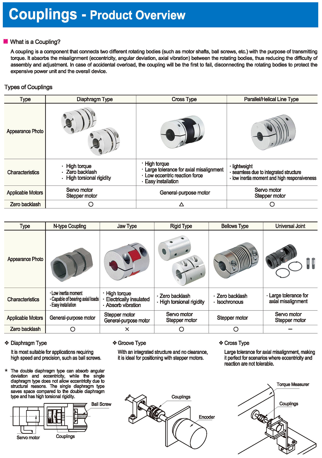
Types of Couplings
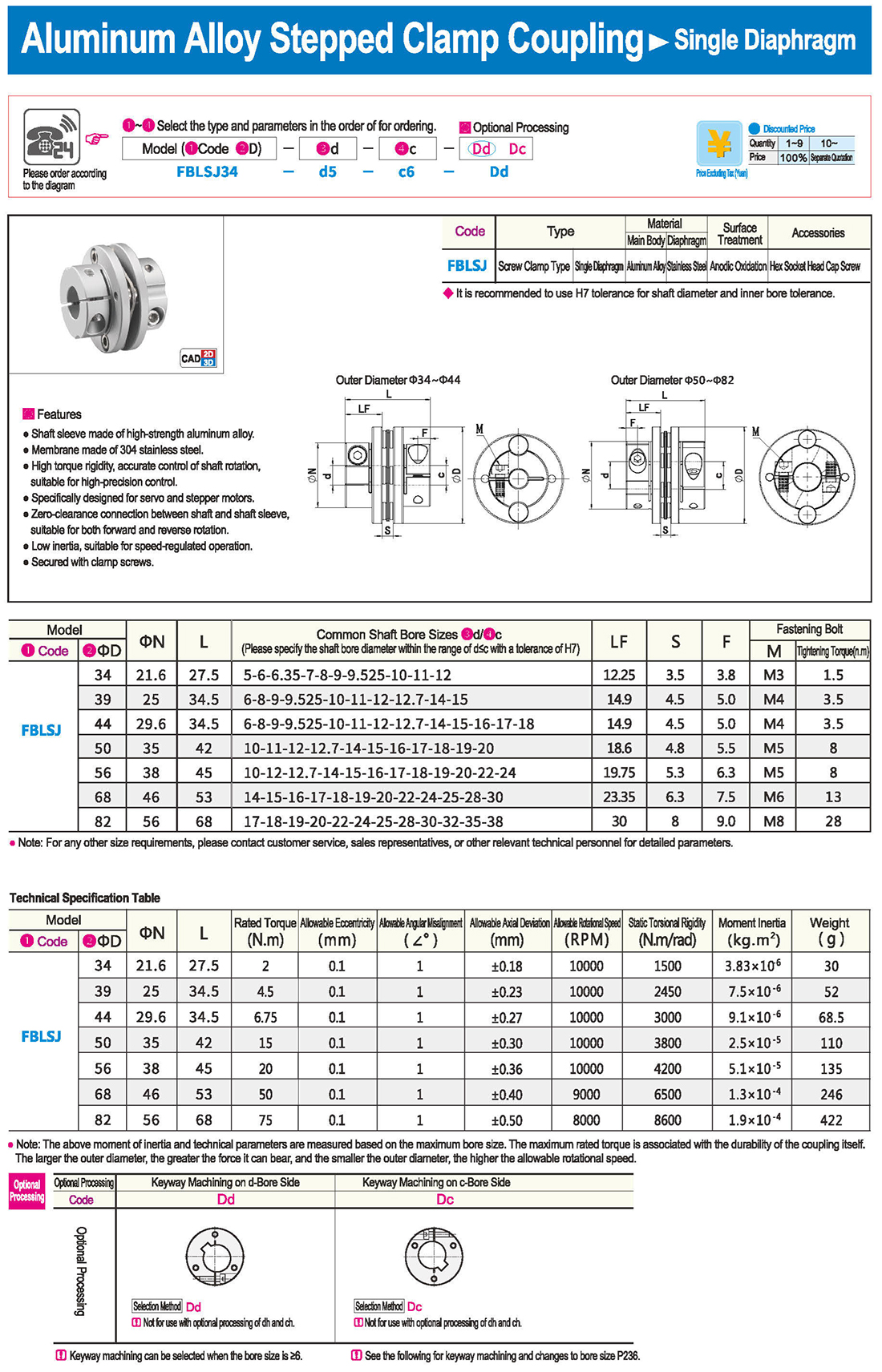
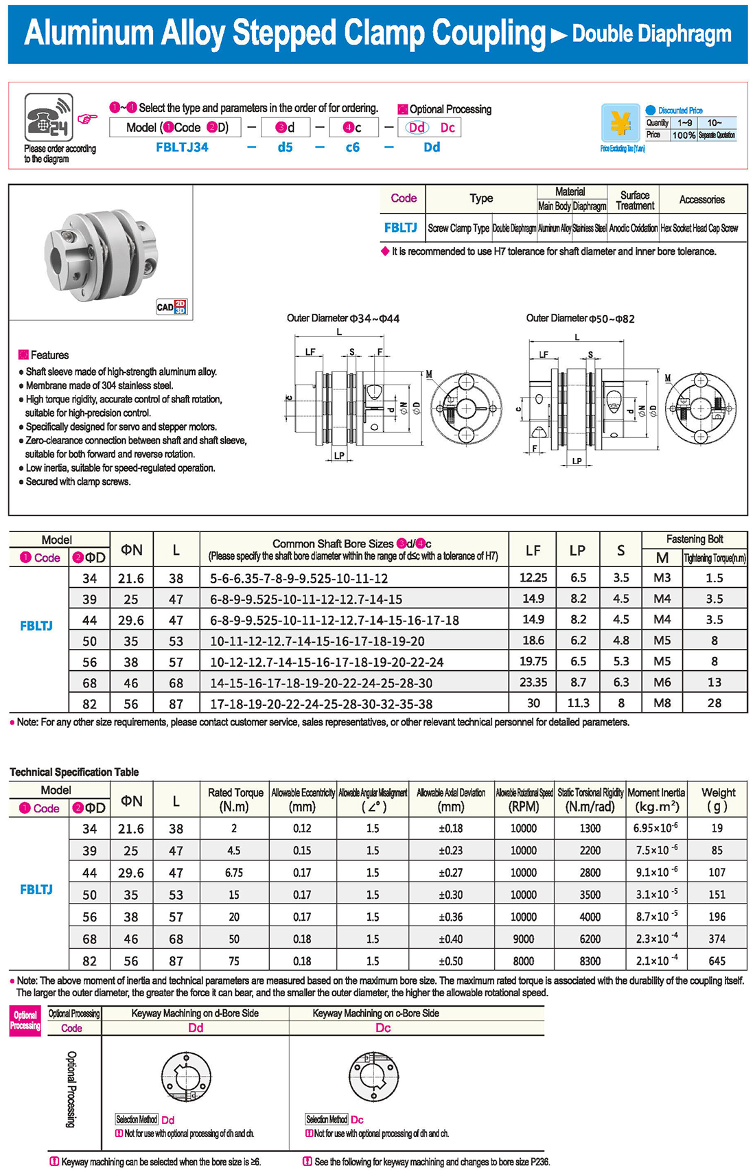
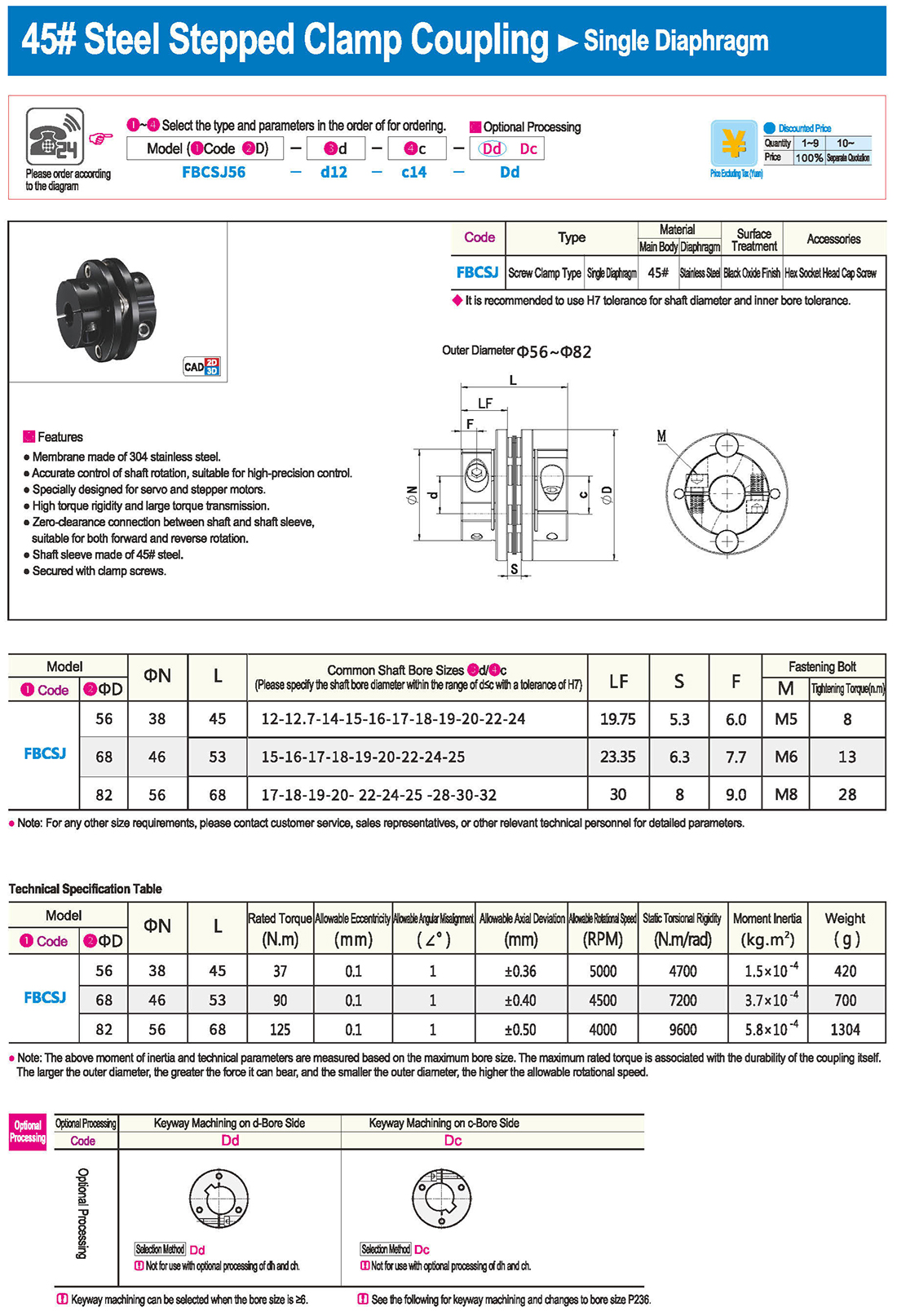
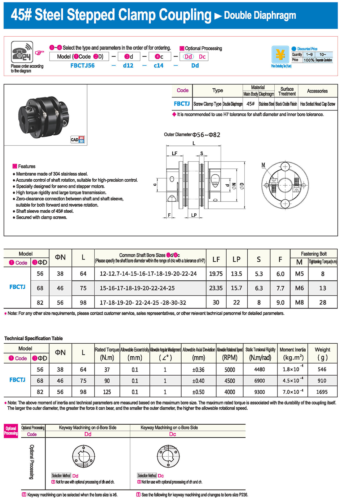
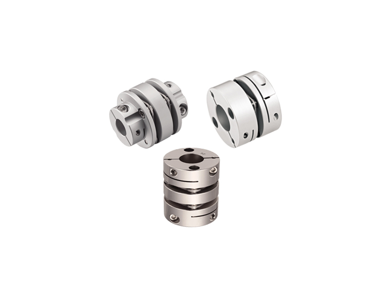
Type: Diaphragm Type, Cross Type, Parallel/Helical Line Type
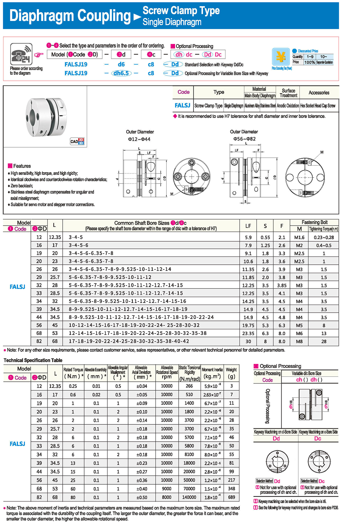
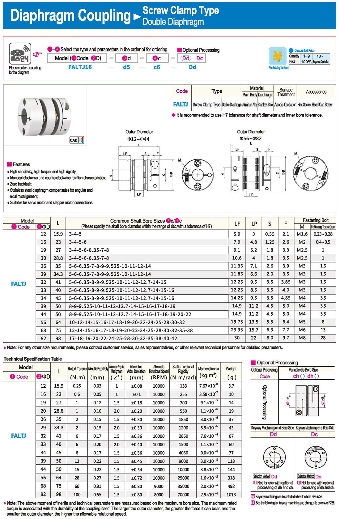
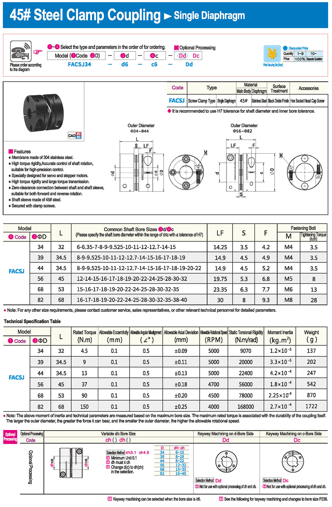
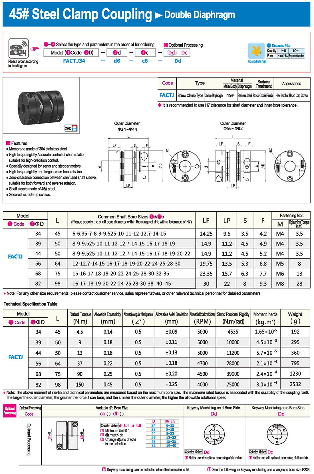
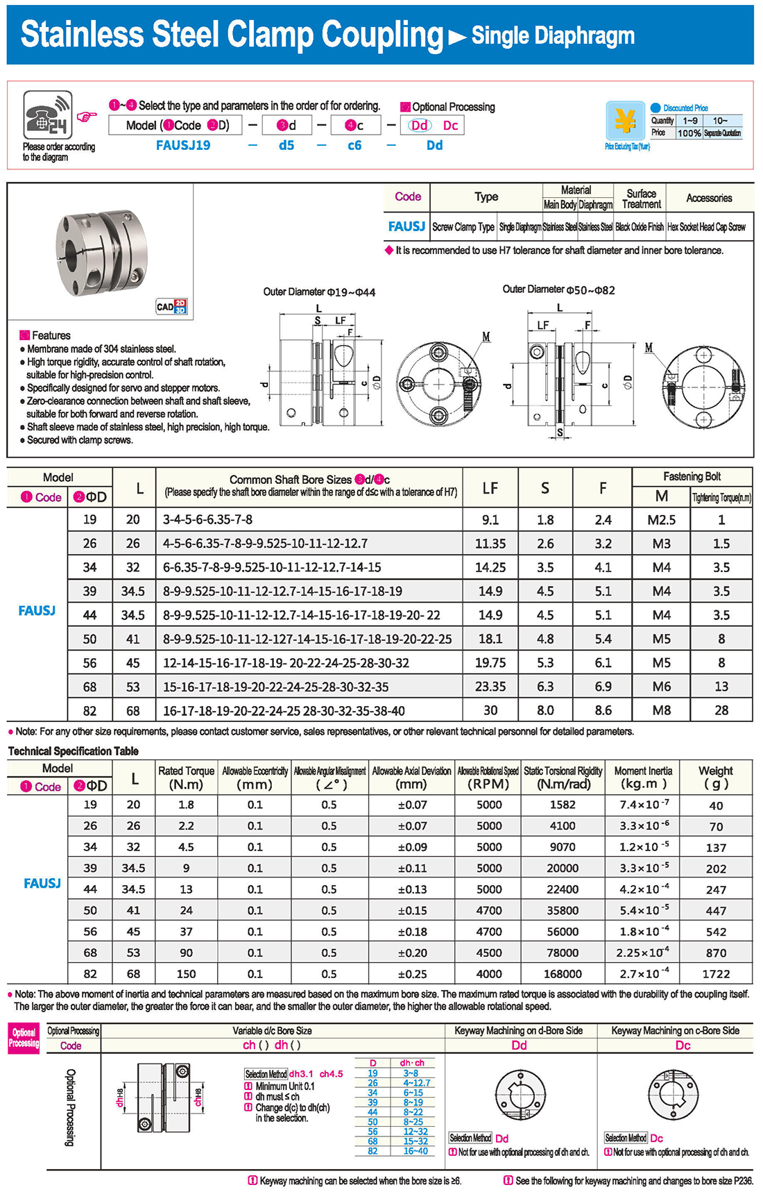
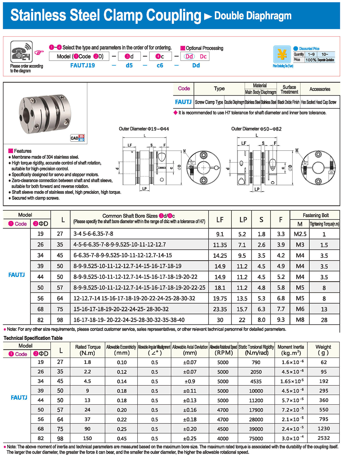
It is most suitable for applications requiring high speed and precision, such as ball screws.
Groove Type
With an integrated structure and no clearance, it is ideal for positioning with stepper motors.
Large tolerance for axial misalignment, making it perfect for scenarios where eccentricity and reaction are not tolerable.
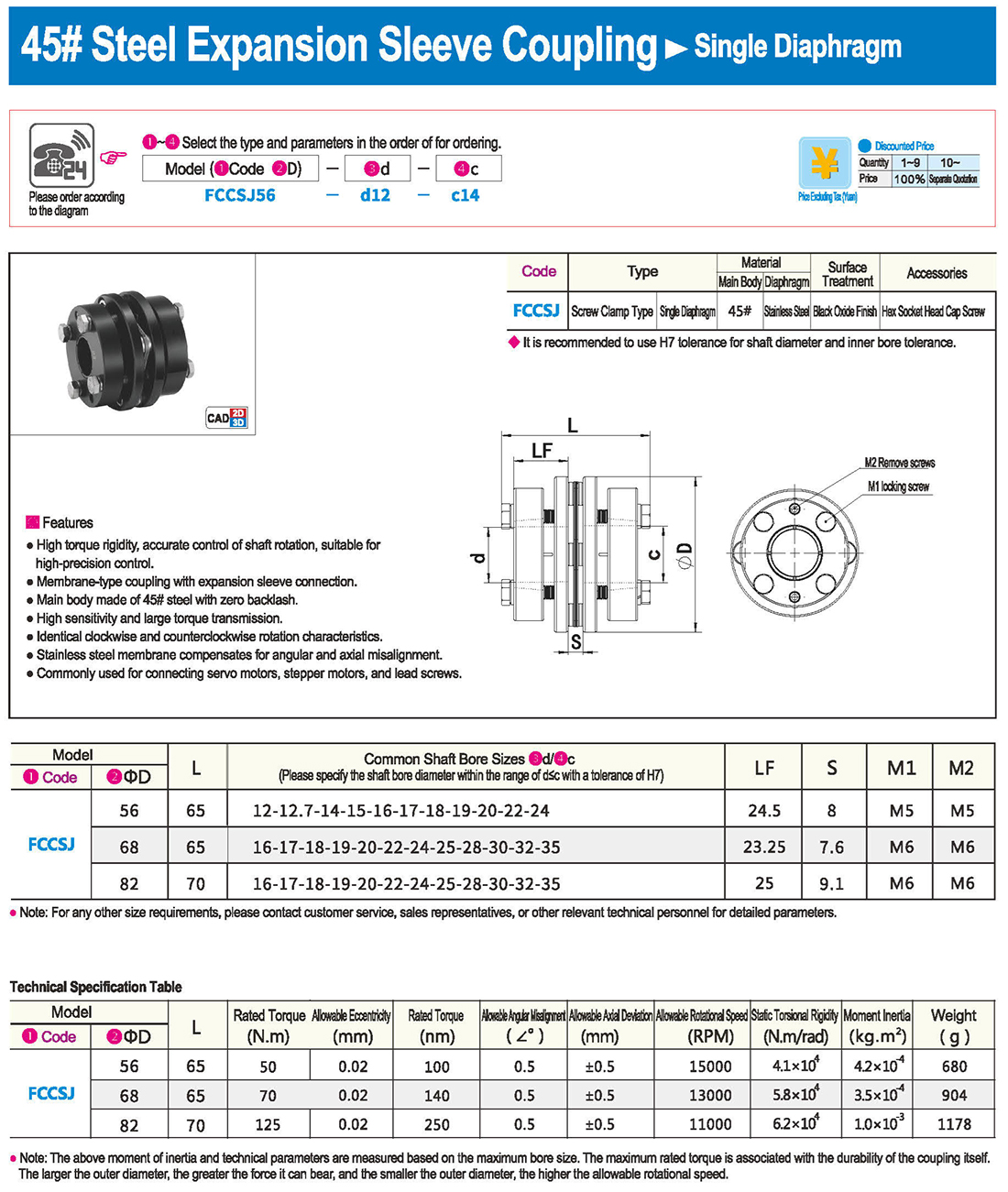
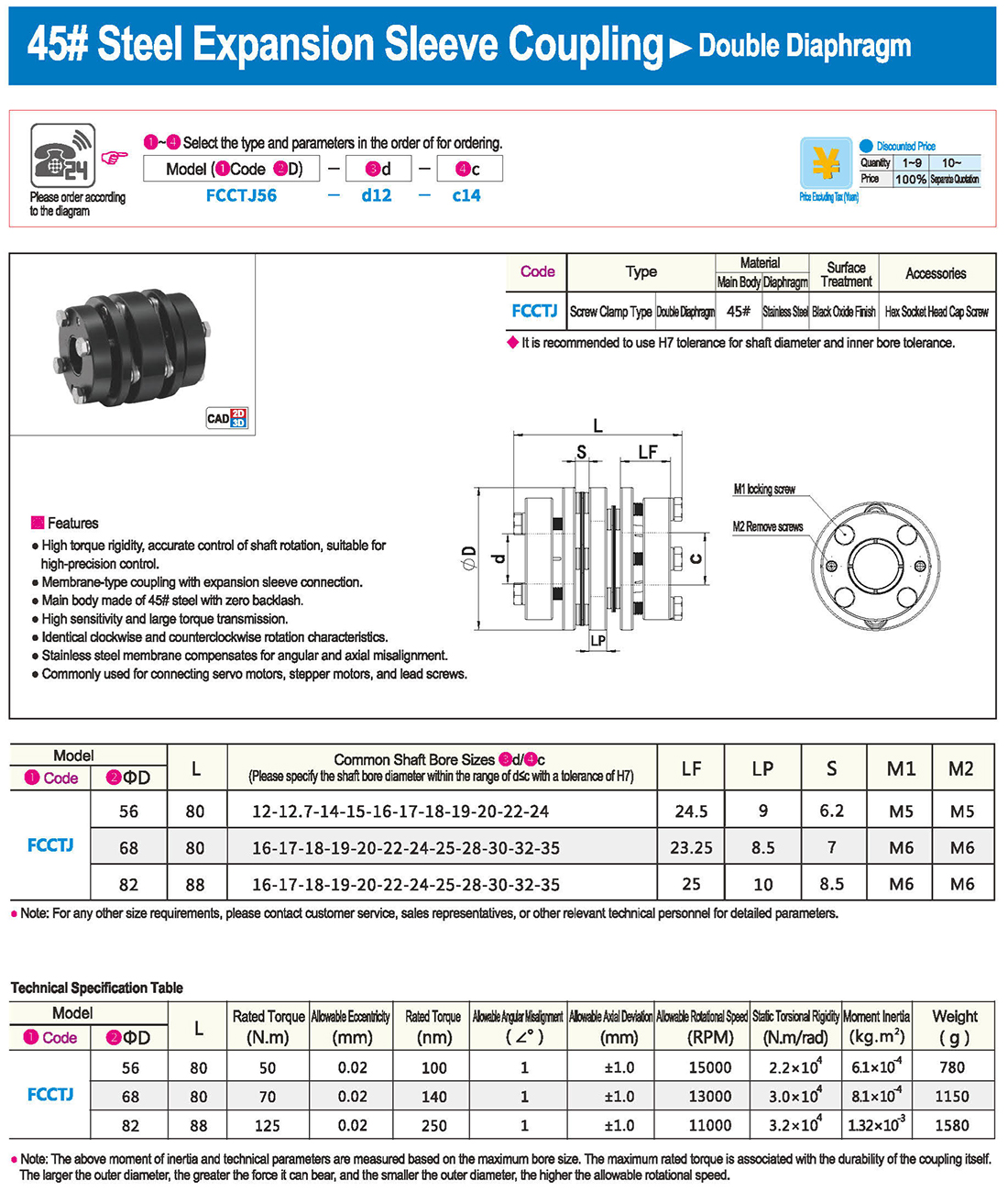
* The double diaphragm type can absorb angular deviation and eccentricity, while the single diaphragm type does not allow eccentricity due to structural reasons. The single diaphragm type saves space compared to the double diaphragm type and has high torsional rigidity.
Encoder & Torque Measurer
When selecting based on the motor, please choose the appropriate coupling type based on the type and application of the motor.
* The combinations of motor types and coupling types are not limited to the ones shown below. Please refer to the individual product pages before making a selection.
* When selecting based on torque, please start from step 2.
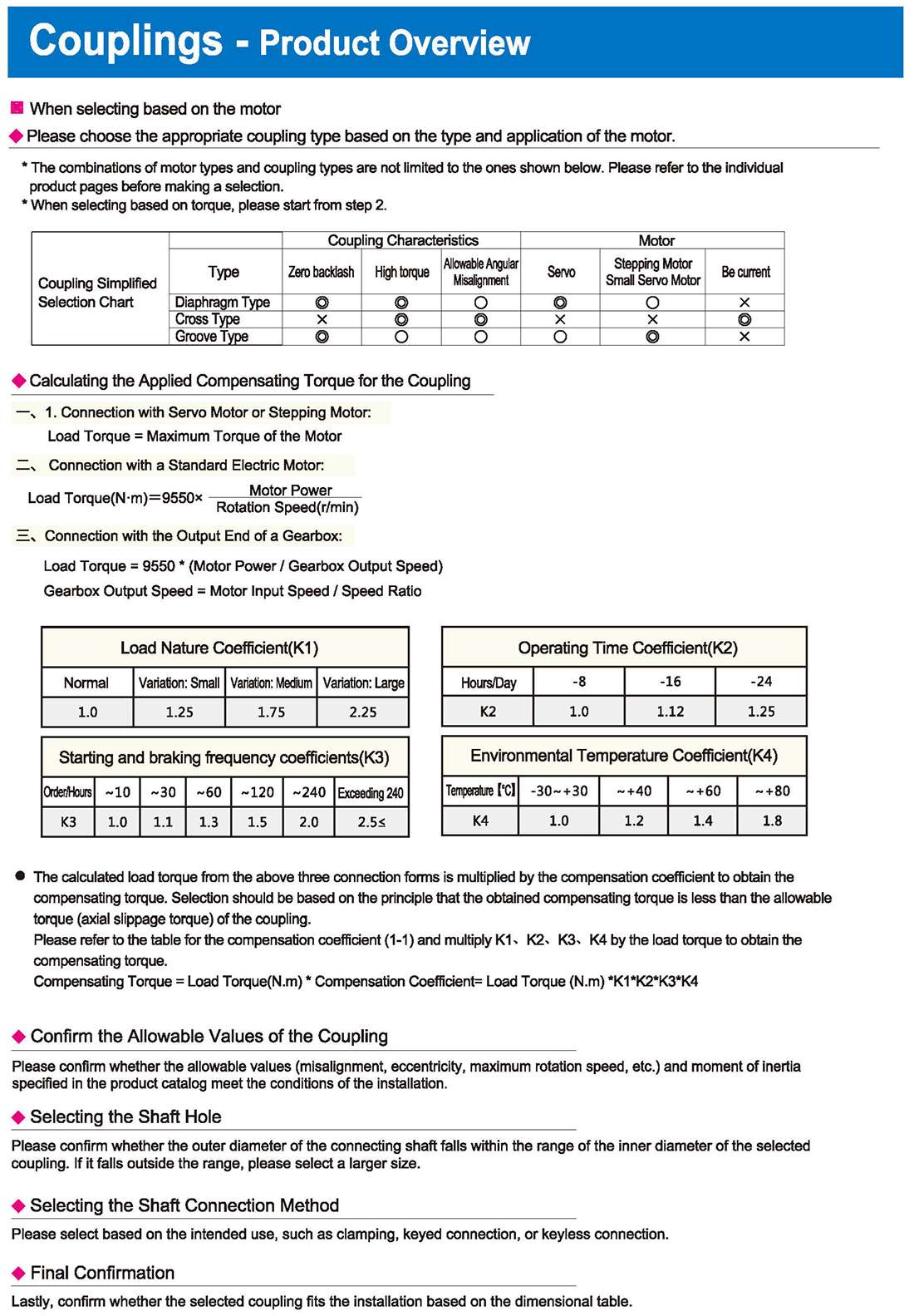
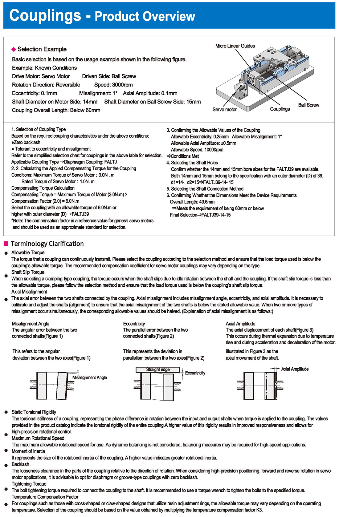
Coupling Simplified Selection Chart
Diaphragm Type Coupling Characteristics Allowable Angular Misalignment Motor Stepping Motor, Small Servo Motor
Calculating the Applied Compensating Torque for the Coupling
1. Connection with Servo Motor or Stepping Motor: Load Torque = Maximum Torque of the Motor
2. Connection with a Standard Electric Motor: Load Torque, Motor Power, Rotation Speed
3. Connection with the Output End of a Gearbox:
Load Torque = 9550 * (Motor Power / Gearbox Output Speed) Gearbox Output Speed = Motor Input Speed / Speed Ratio
Load Nature Coefficient, Operating Time Coefficient, Environmental Temperature Coefficient
Normal, Variation: Small, Medium, Large, Hours/Time, Exceeding, Temperature
The calculated load torque from the above three connection forms is multiplied by the compensation coefficient to obtain the compensating torque. Selection should be based on the principle that the obtained compensating torque is less than the allowable torque (axial slippage torque) of the coupling.
Please refer to the table for the compensation coefficient and multiply K4 by the load torque to obtain the compensating torque.
Compensating Torque = Load Torque * Compensation Coefficient = Load Torque
Confirm the Allowable Values of the Coupling
Please confirm whether the allowable values (misalignment, eccentricity, maximum rotation speed, etc.) and moment of inertia specified in the product catalog meet the conditions of the installation.
Selecting the Shaft Hole
Please confirm whether the outer diameter of the connecting shaft falls within the range of the inner diameter of the selected coupling. If it falls outside the range, please select a larger size.
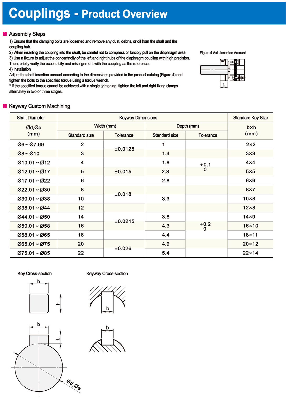
Selecting the Shaft Connection Method
Please select based on the intended use, such as clamping, keyed connection, or keyless connection.
Final Confirmation
Lastly, confirm whether the selected coupling fits the installation based on the dimensional table.


 English
 Russian
 Spanish
 Italian
 Arabic
 Korean
 German
 Japanese
 Vietnamese
 Turkish
 Introduction
 Specification Table
 Download


