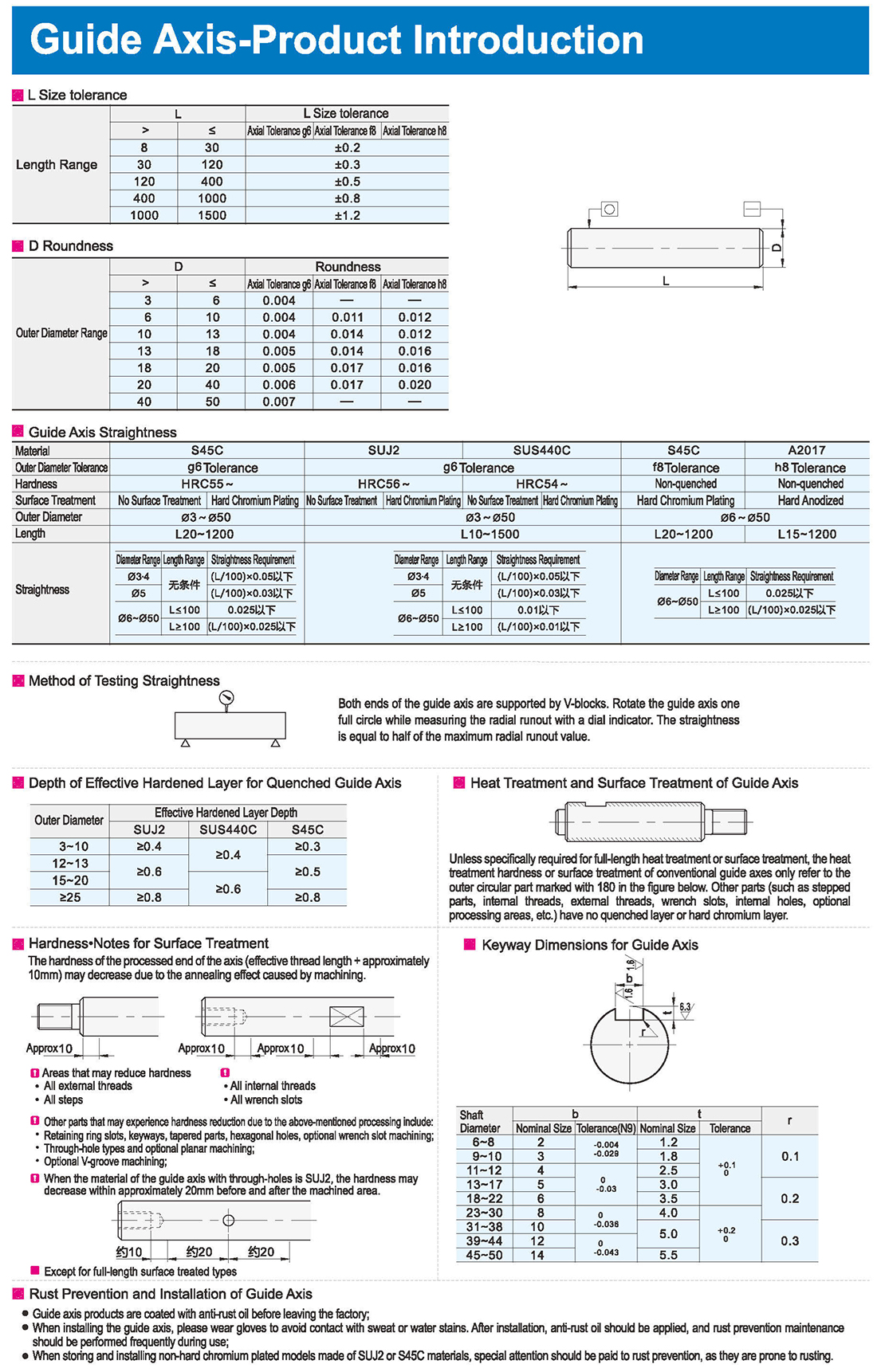
1.Depth of Effective Hardened Layer for Quenched Guide Axis
2.Heat Treatment and Surface Treatment of Guide Axis。
Unless specifically required for full-length heat treatment or surface treatment, the heat treatment hardness or surface treatment of conventional guide axes only refer to the outer circular part marked with 180 in the figure below. Other parts (such as stepped parts, internal threads, external threads, wrench slots, internal holes, optional processing areas, etc.) have no quenched layer or hard chromium layer.
3.Rust Prevention and Installation of Guide Axis
Guide axis products are coated with anti-rust oil before leaving the factory;
When installing the guide axis, please wear gloves to avoid contact with sweat or water stains. After installation, anti-rust oil should be applied, and rust prevention maintenance should be performed frequently during use;
When storing and installing non-hard chromium plated models made of SUJ2 or S45C materials, special attention should be paid to rust prevention, as they are prone to rusting.
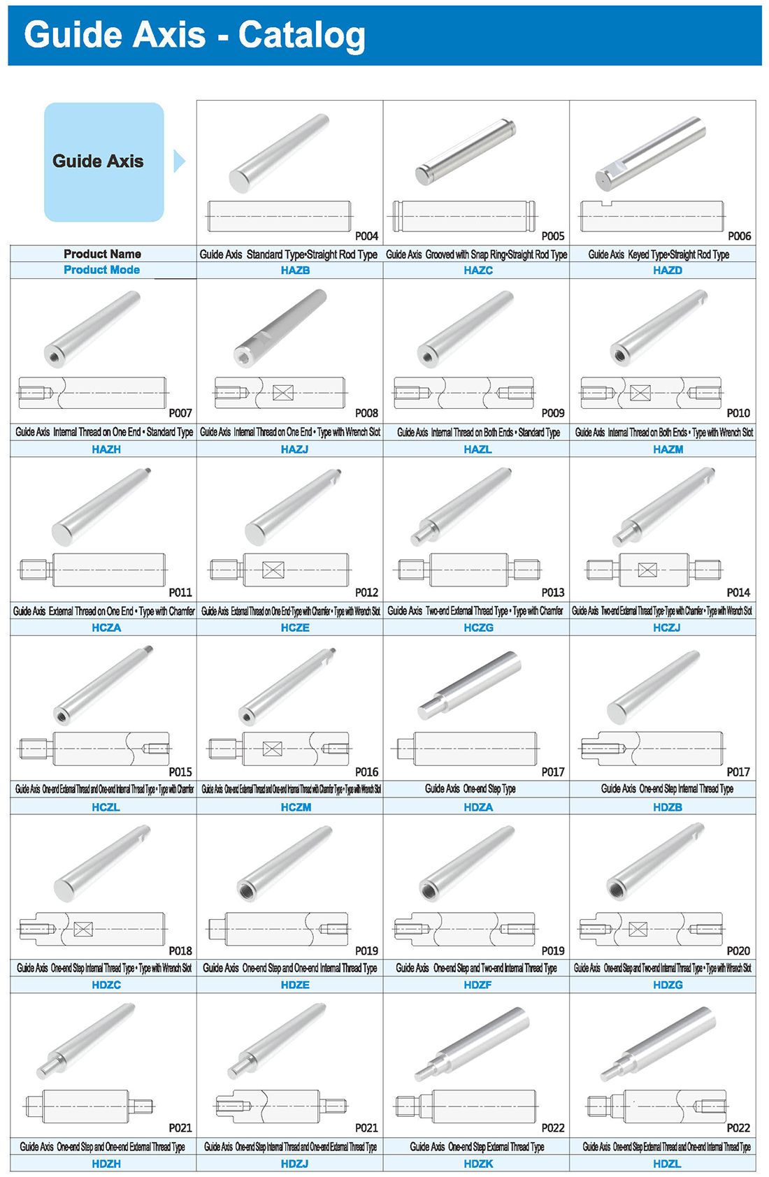
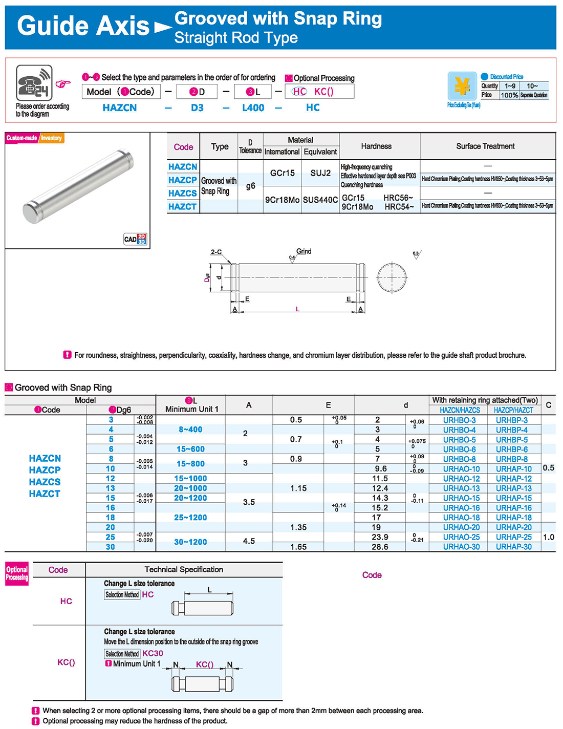
1.Grooved with Snap Ring
Cancel snap ring groove on one end Move the L dimension position to the outside of the snap ring groove
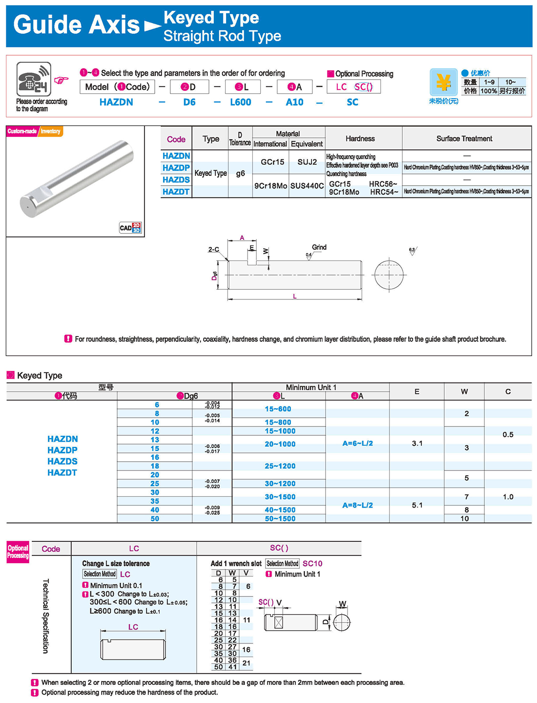
2.Keyed Type Internal Thread on One End
Precision Grade Ordinary Grade Precision Grade
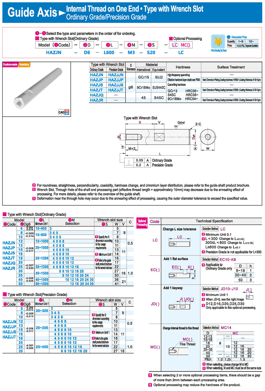
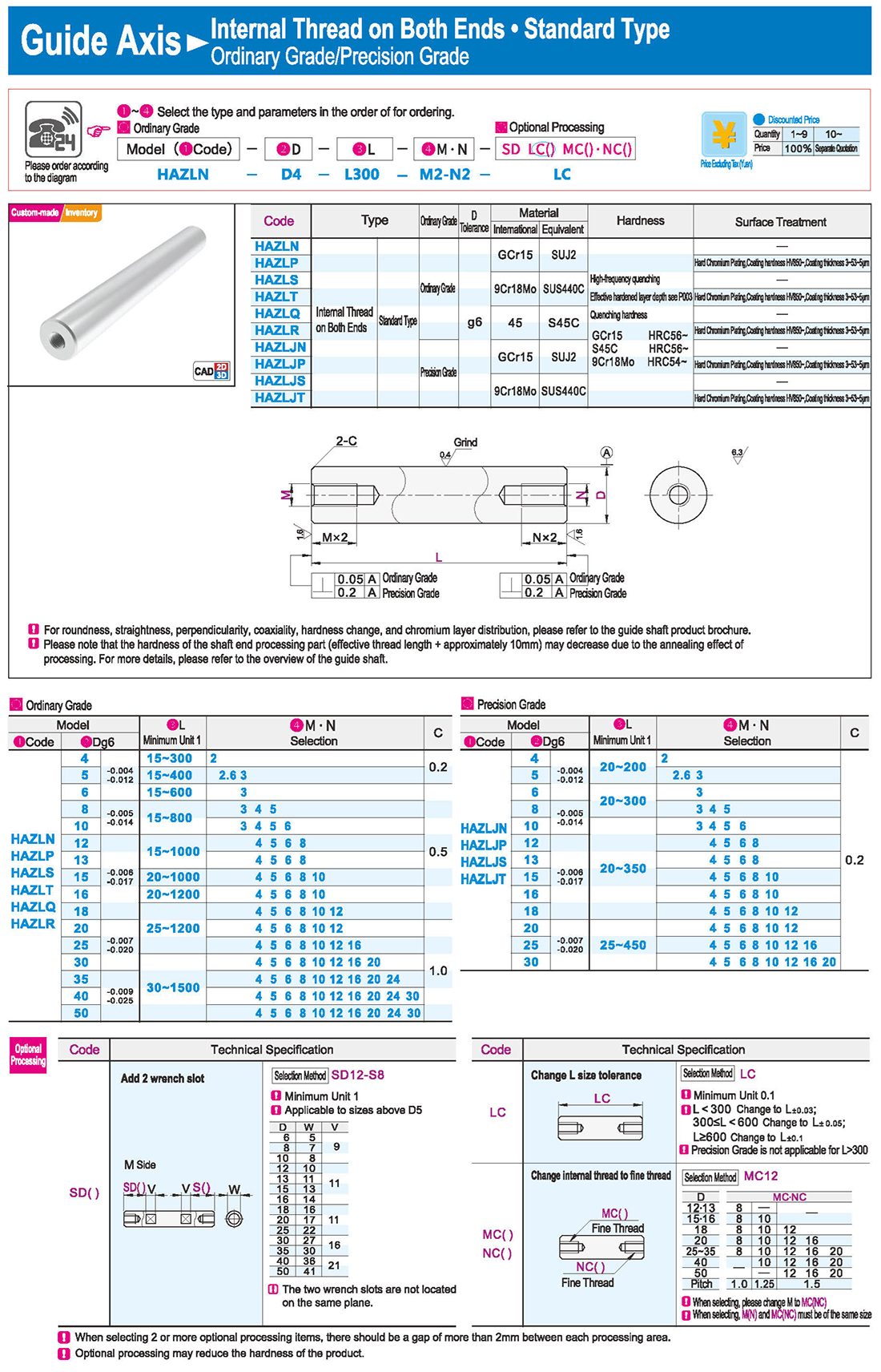
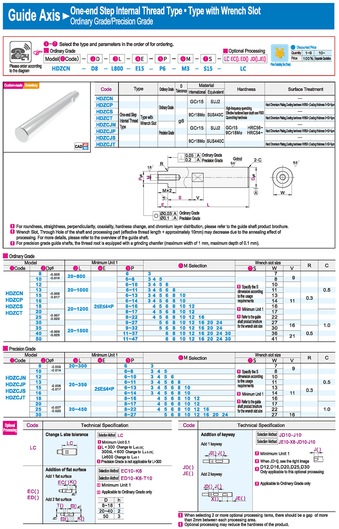
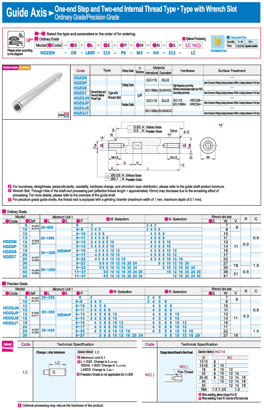
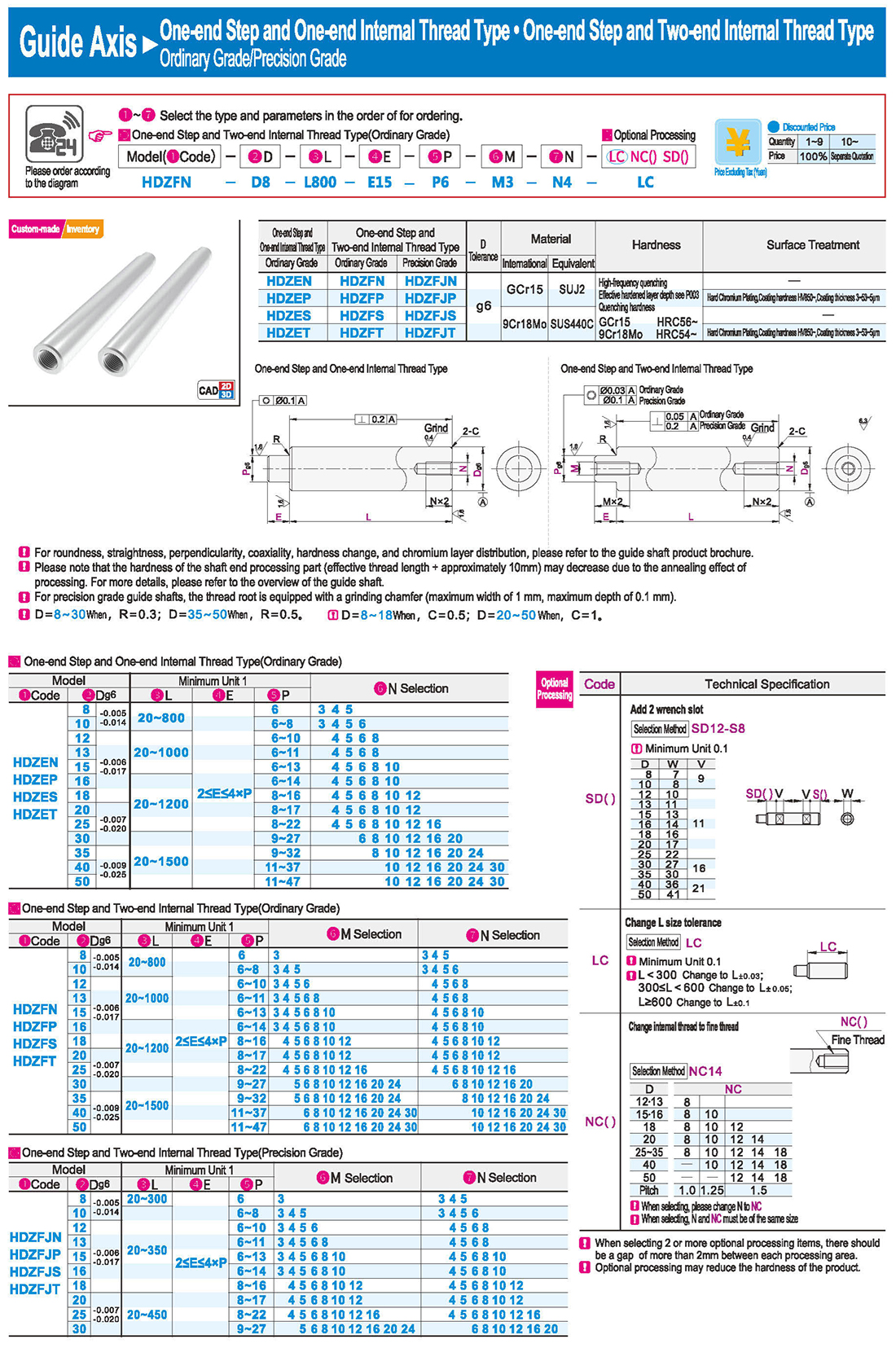
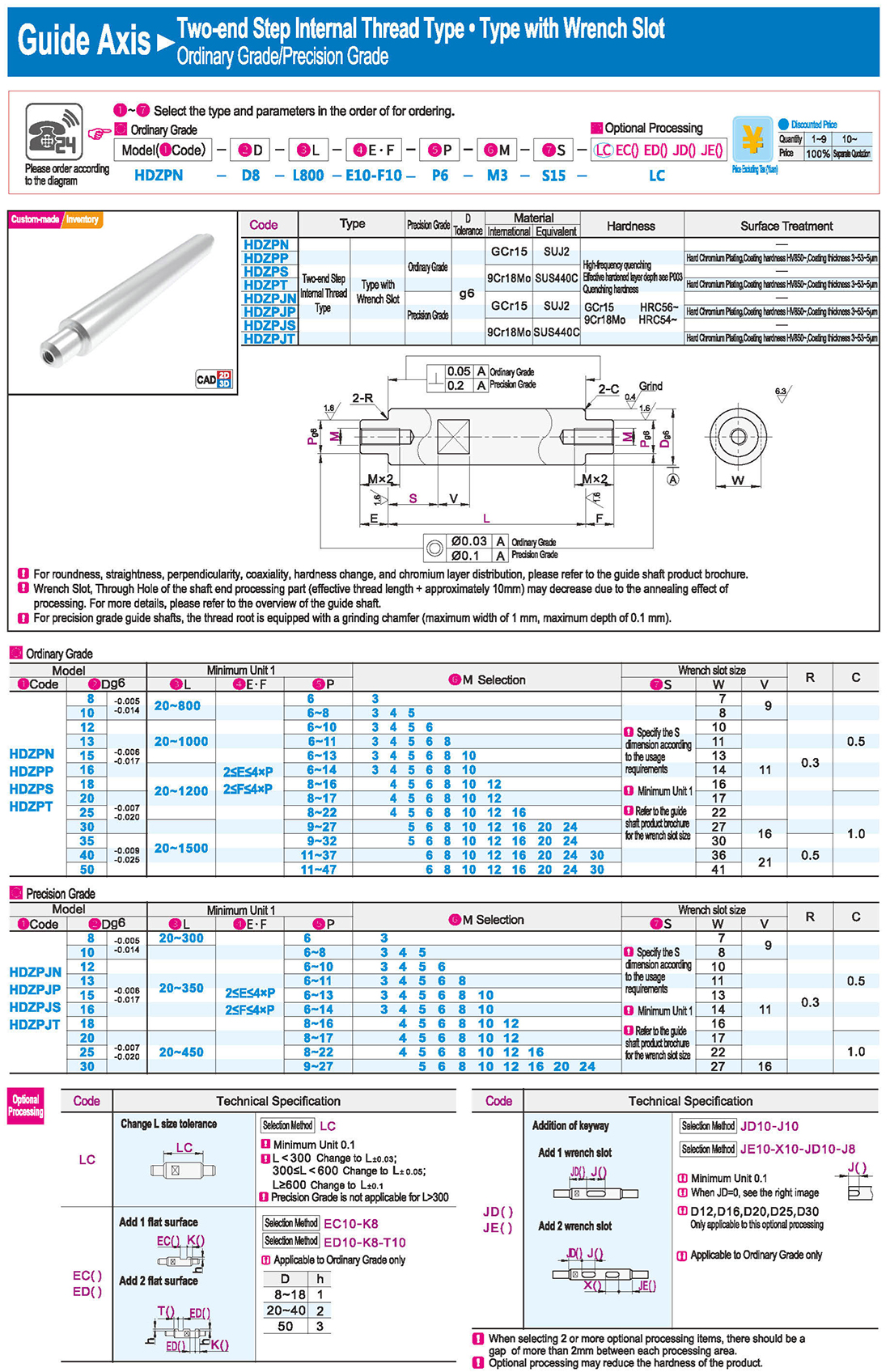
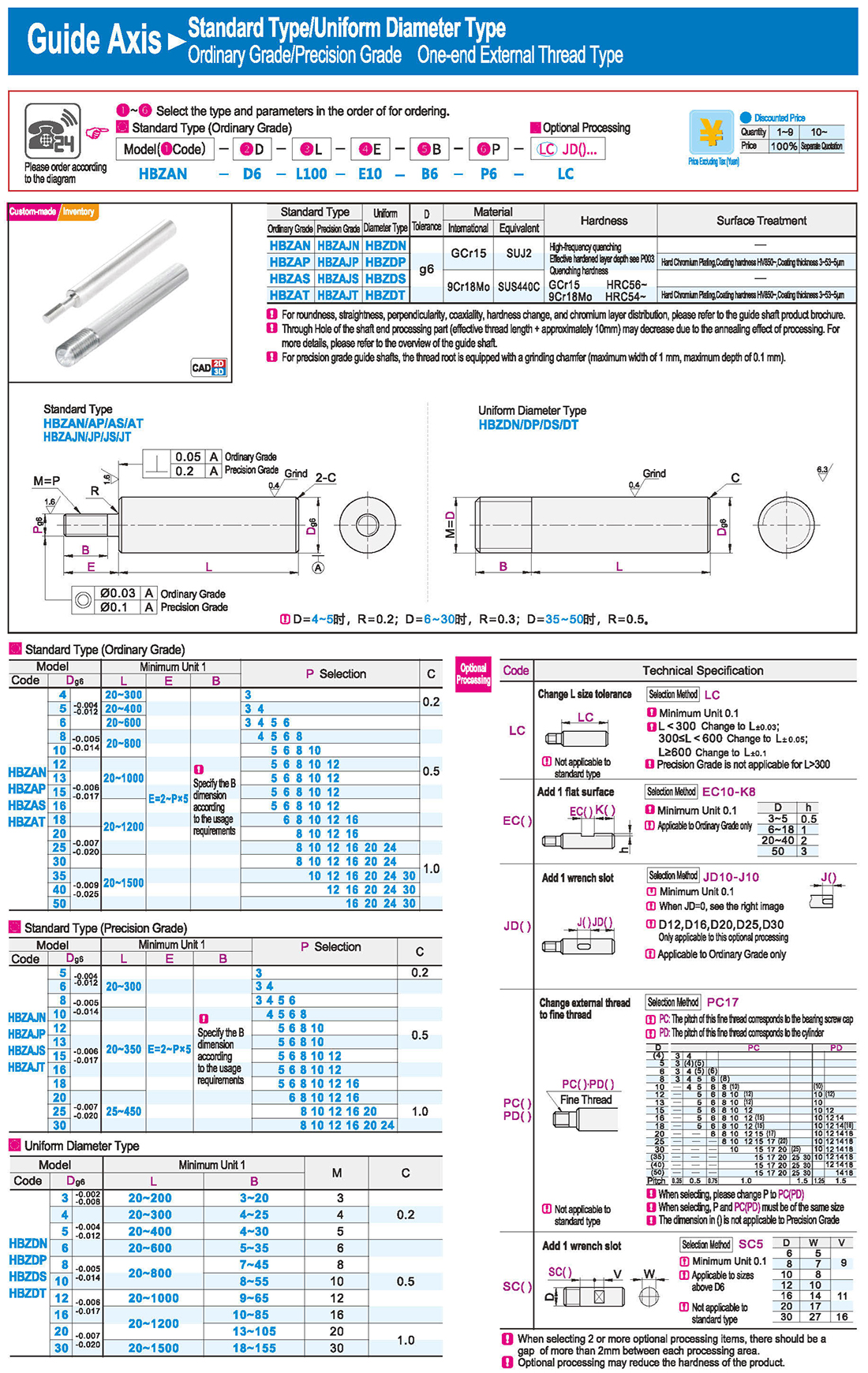
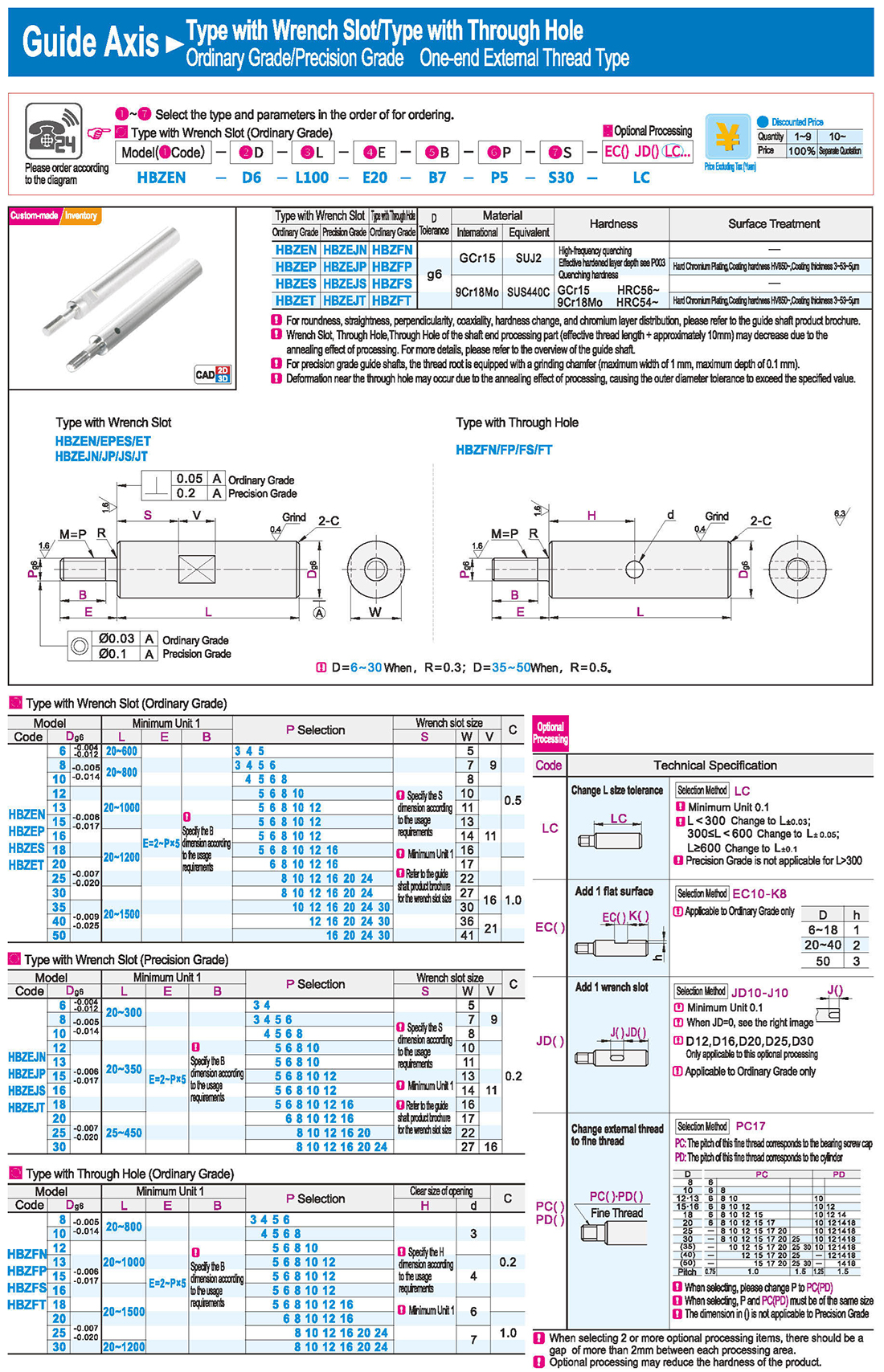
Please note that the hardness of the shaft end processing part (effective thread length + approximately 10mm) may decrease due to the annealing effect of processing. For more details, please refer to the overview of the guide shaft.
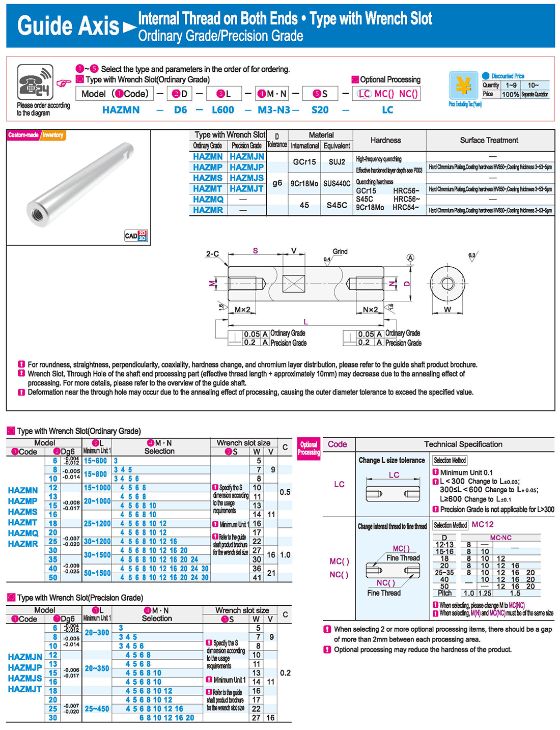
Selection: Precision Grade is not applicable for L>300
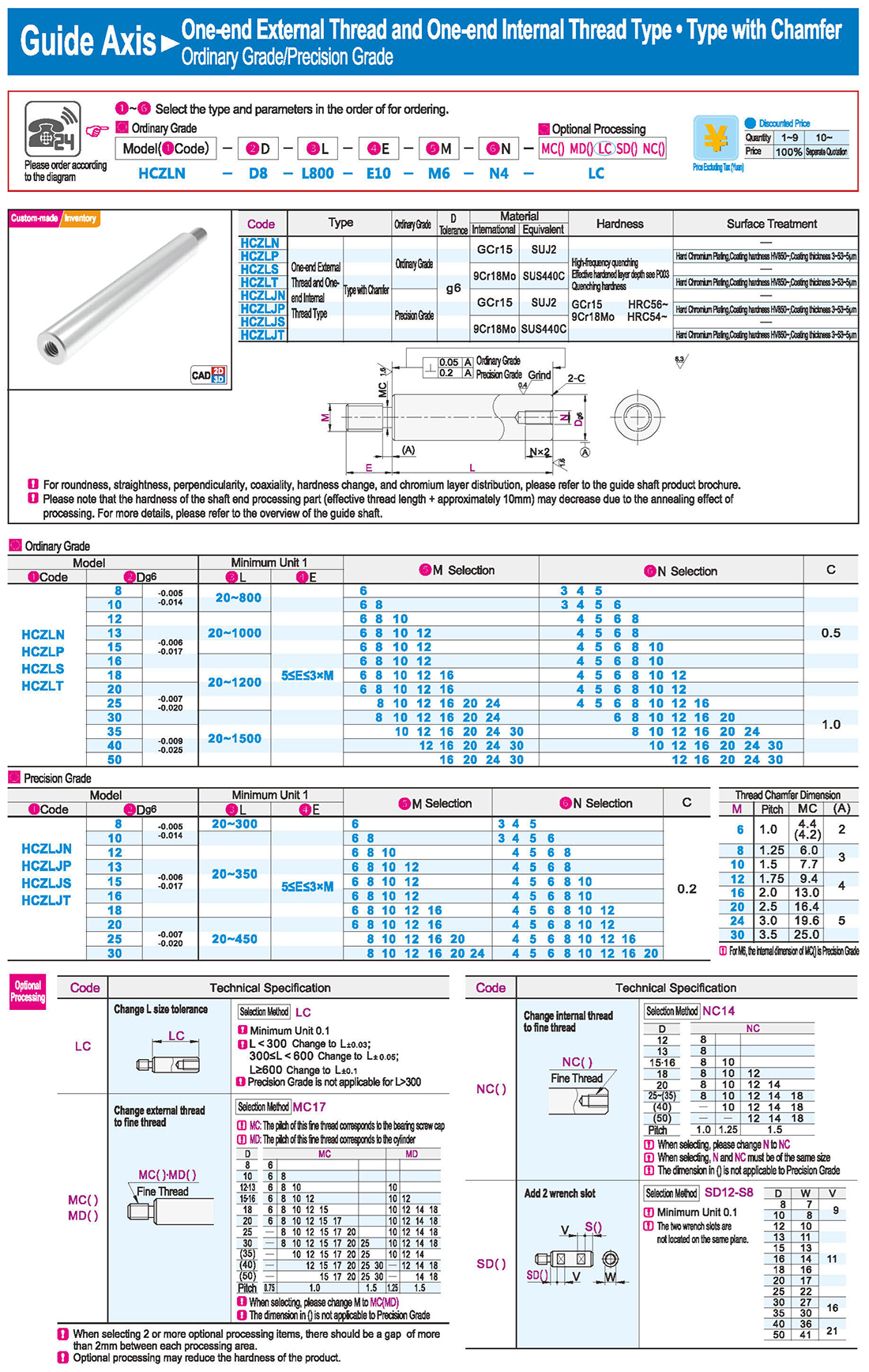
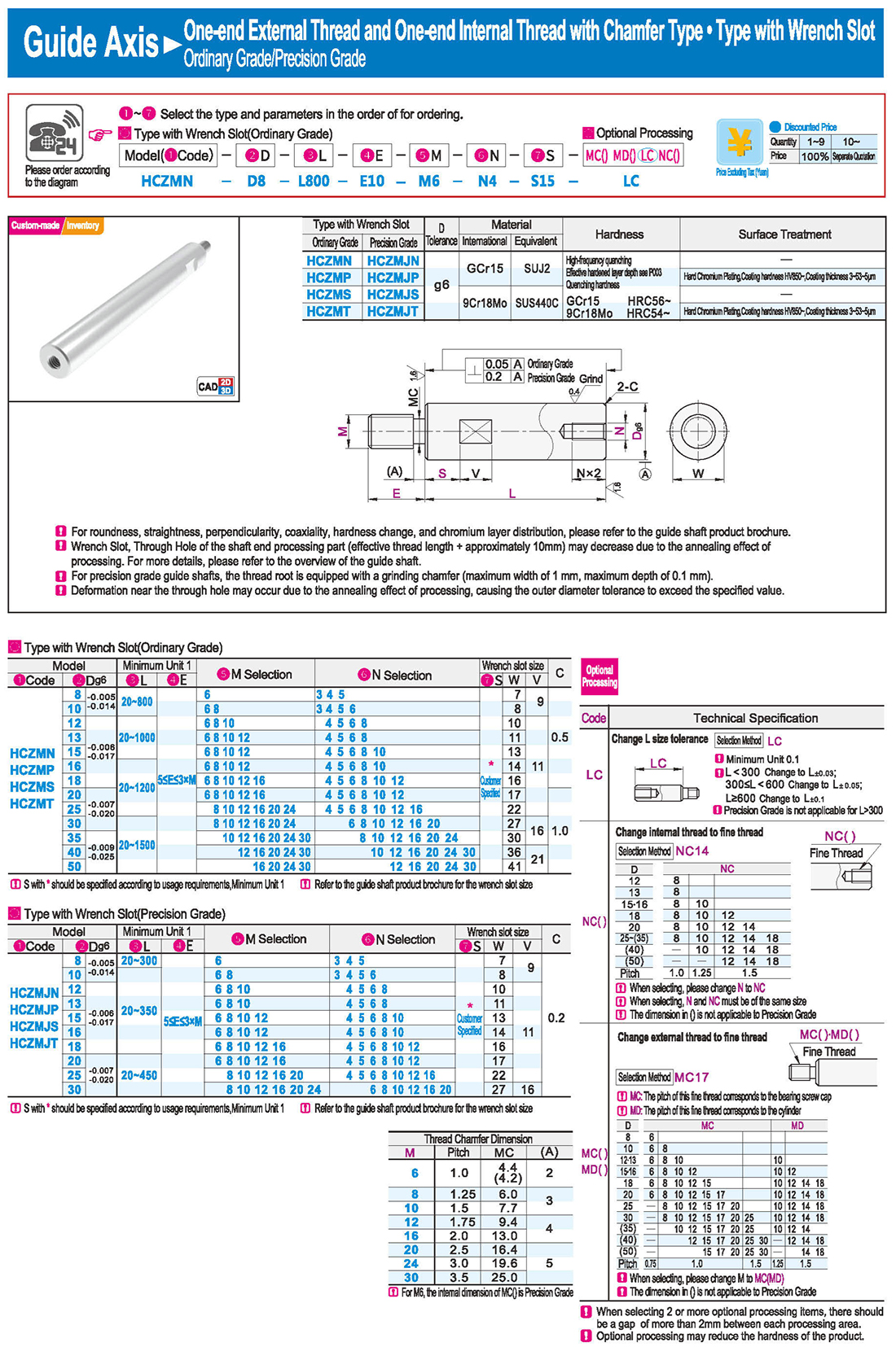
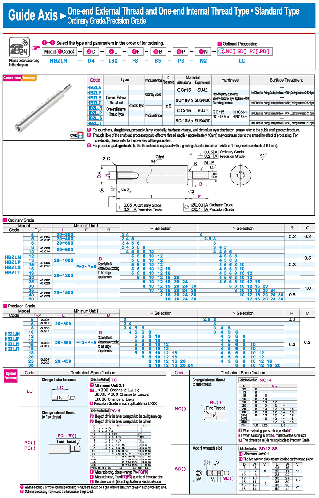
Change internal thread to fine thread Pitch Fine Thread
When selecting, please change M to MC
M and MC must be of the same size
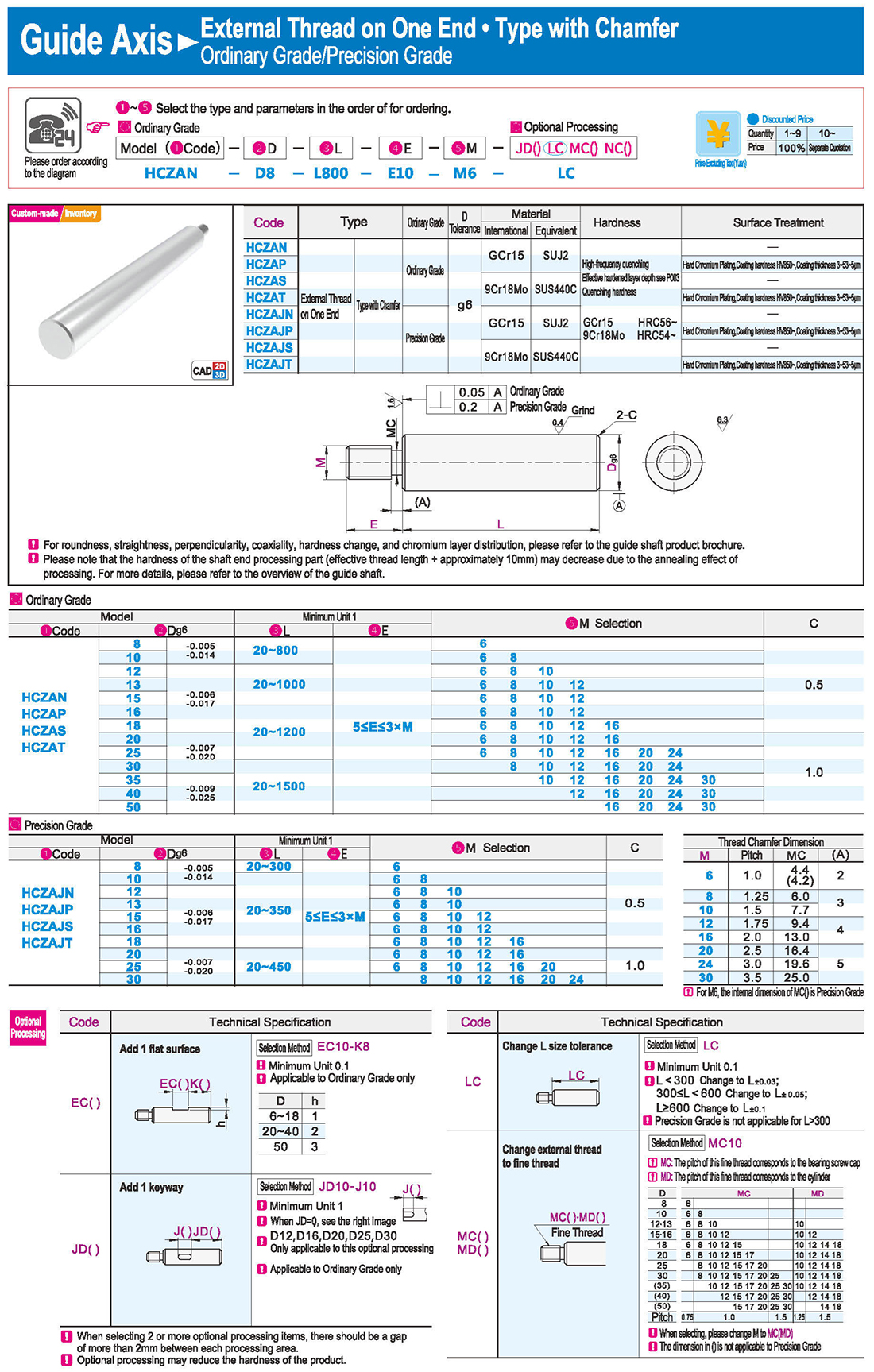
Applicable to Ordinary Grade only
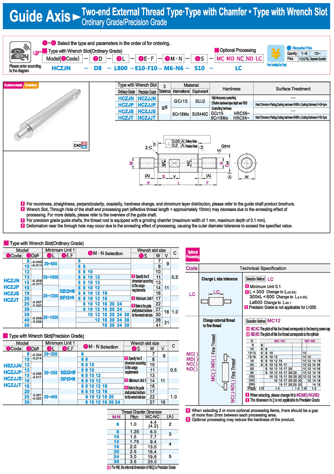
3.Type with Wrench Slot
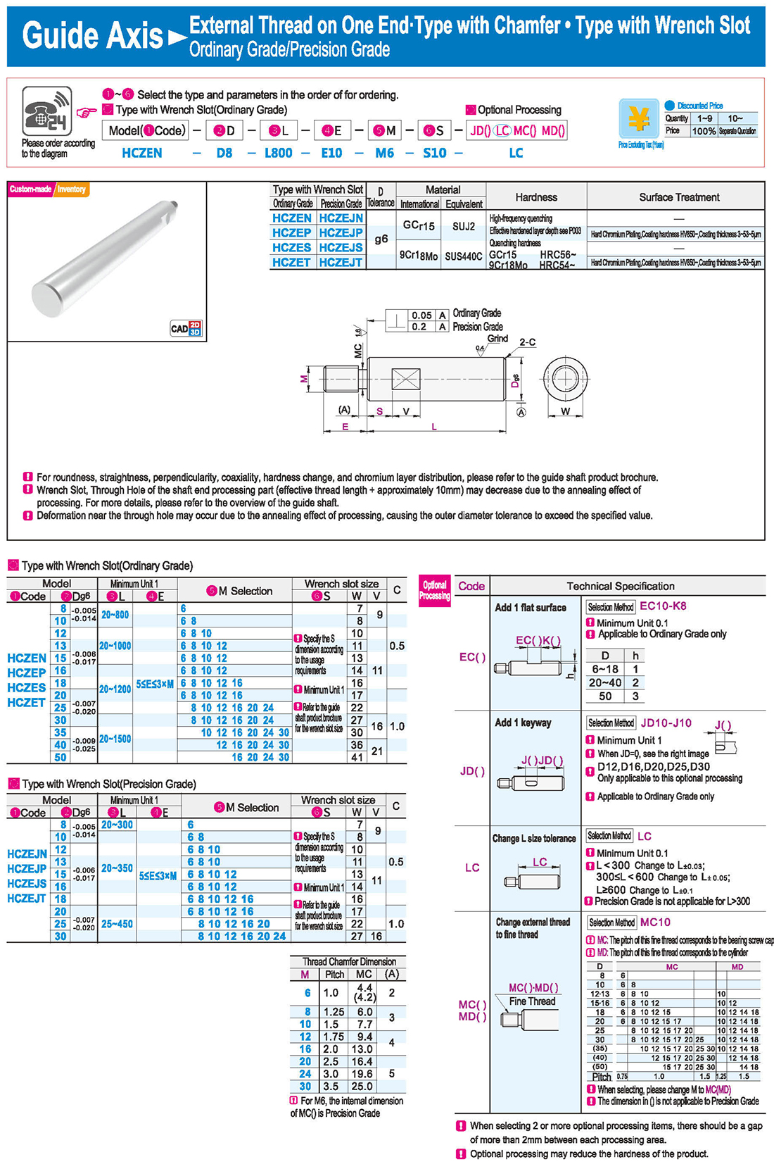
Deformation near the through hole may occur due to the annealing effect of processing, causing the outer diameter tolerance to exceed the specified value.
Specify the S dimension according to the usage requirements
Refer to the guide shaft product brochure for the wrench slot size
4.Internal Thread on Both Ends
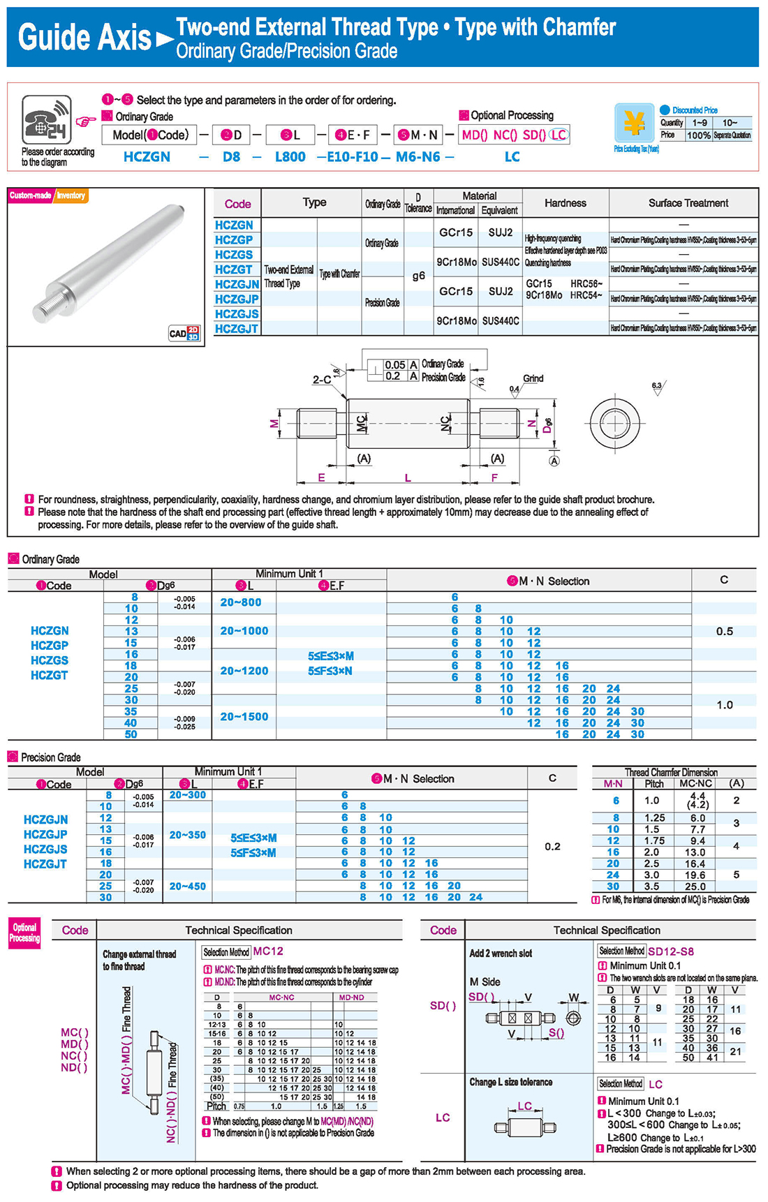
The two wrench slots are not located on the same plane.
5.External Thread on One End · Type with Chamfer
Thread Chamfer Dimension
For M6, the internal dimension of MC() is Precision Grade
MC: The pitch of this fine thread corresponds to the bearing screw cap
MD: The pitch of this fine thread corresponds to the cylinder
The dimension in () is not applicable to Precision Grade
6.One-end External Thread and One-end Internal Thread with Chamfer Type
Customer Specified
S with * should be specified according to usage requirements
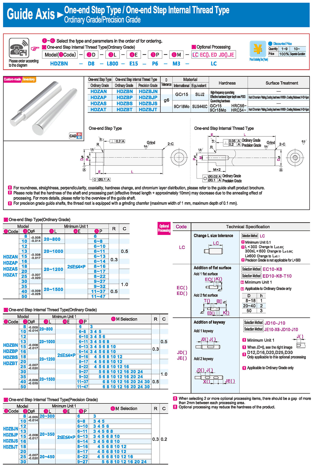
7.One-end Step Type / One-end Step Internal Thread Type
One-end Step Type / One-end Step Internal Thread Type
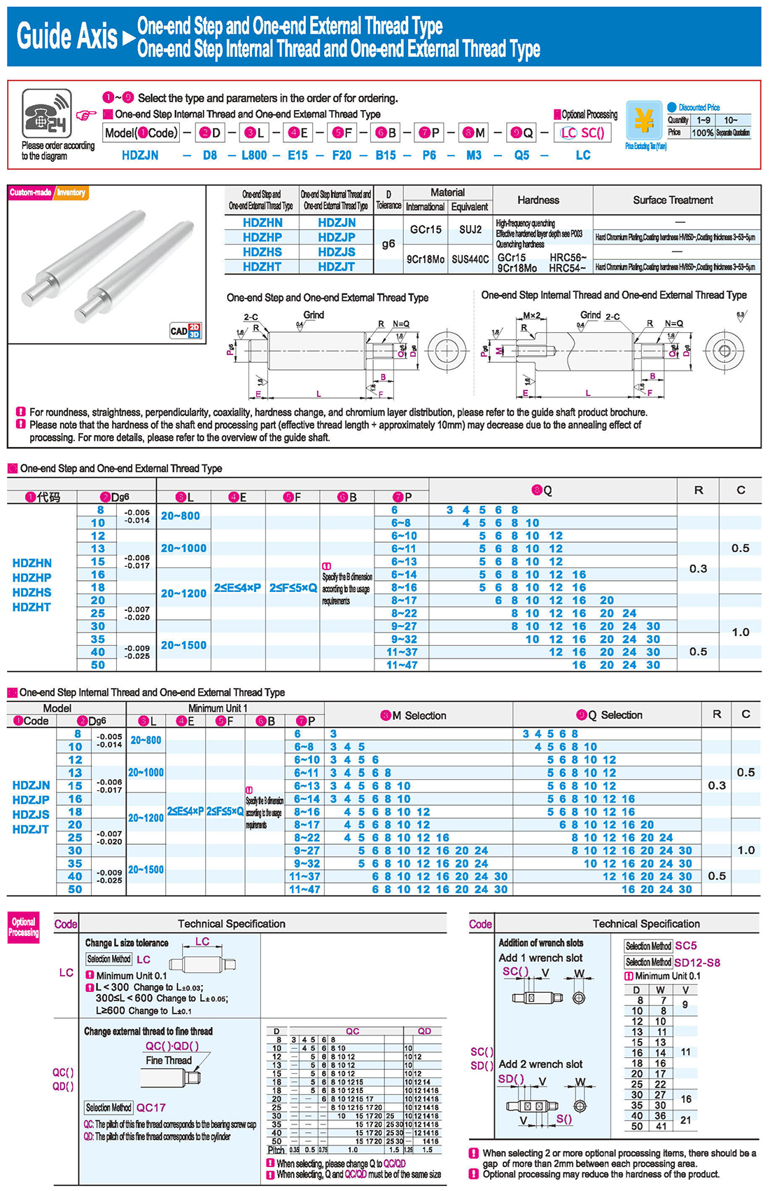
One-end Step and One-end Internal Thread Type · One-end Step and Two-end Internal Thread Type
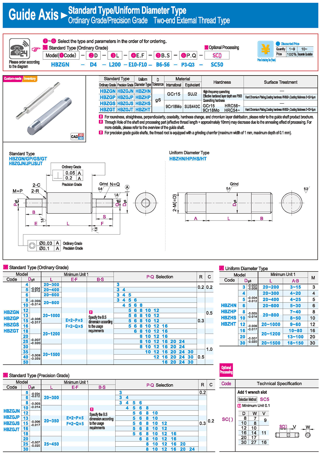
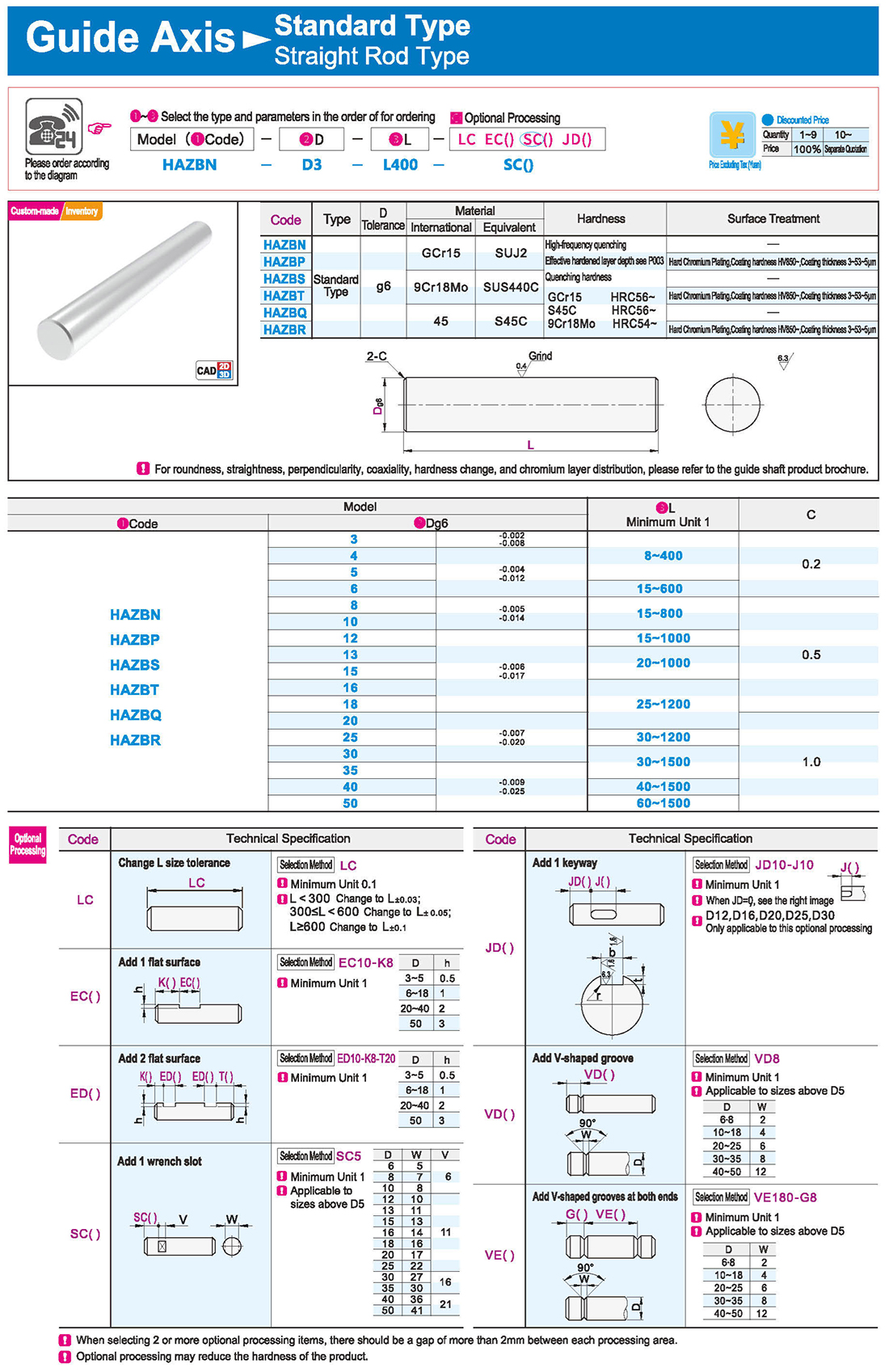
Optional processing may reduce the hardness of the product
One-end Step and One-end External Thread Type
One-end Step Internal Thread and One-end External Thread Type
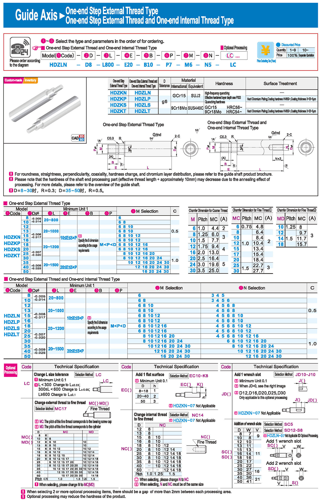
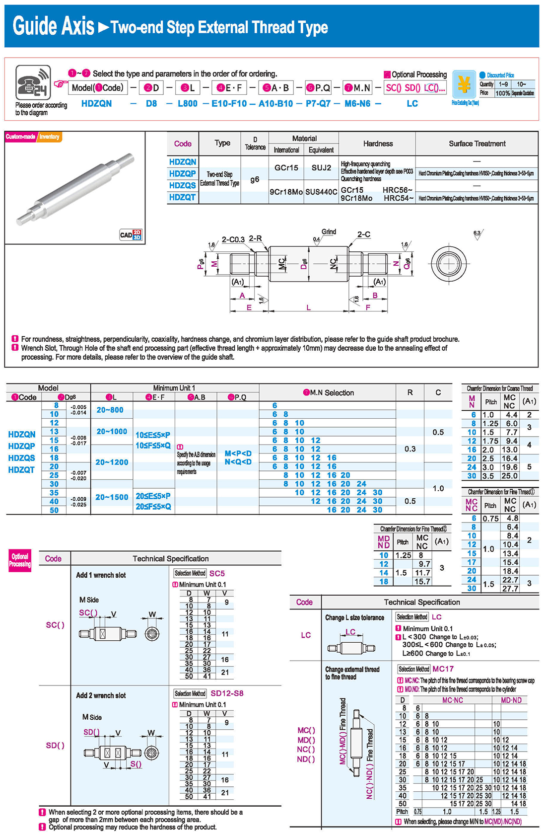
Change external thread to fine thread
One-end Step External Thread Type
One-end Step External Thread and One-end Internal Thread Type
Chamfer Dimension for Coarse Thread
Chamfer Dimension for Fine Thread
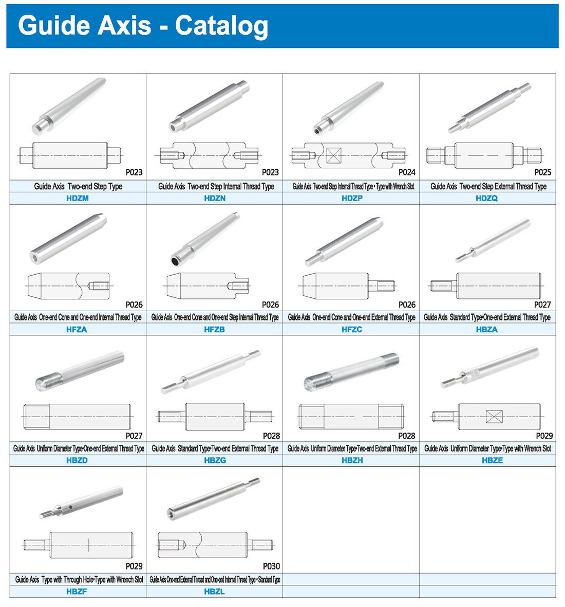
Two-end Step Type · Two-end Step Internal Thread Type
Two-end Step External Thread Type
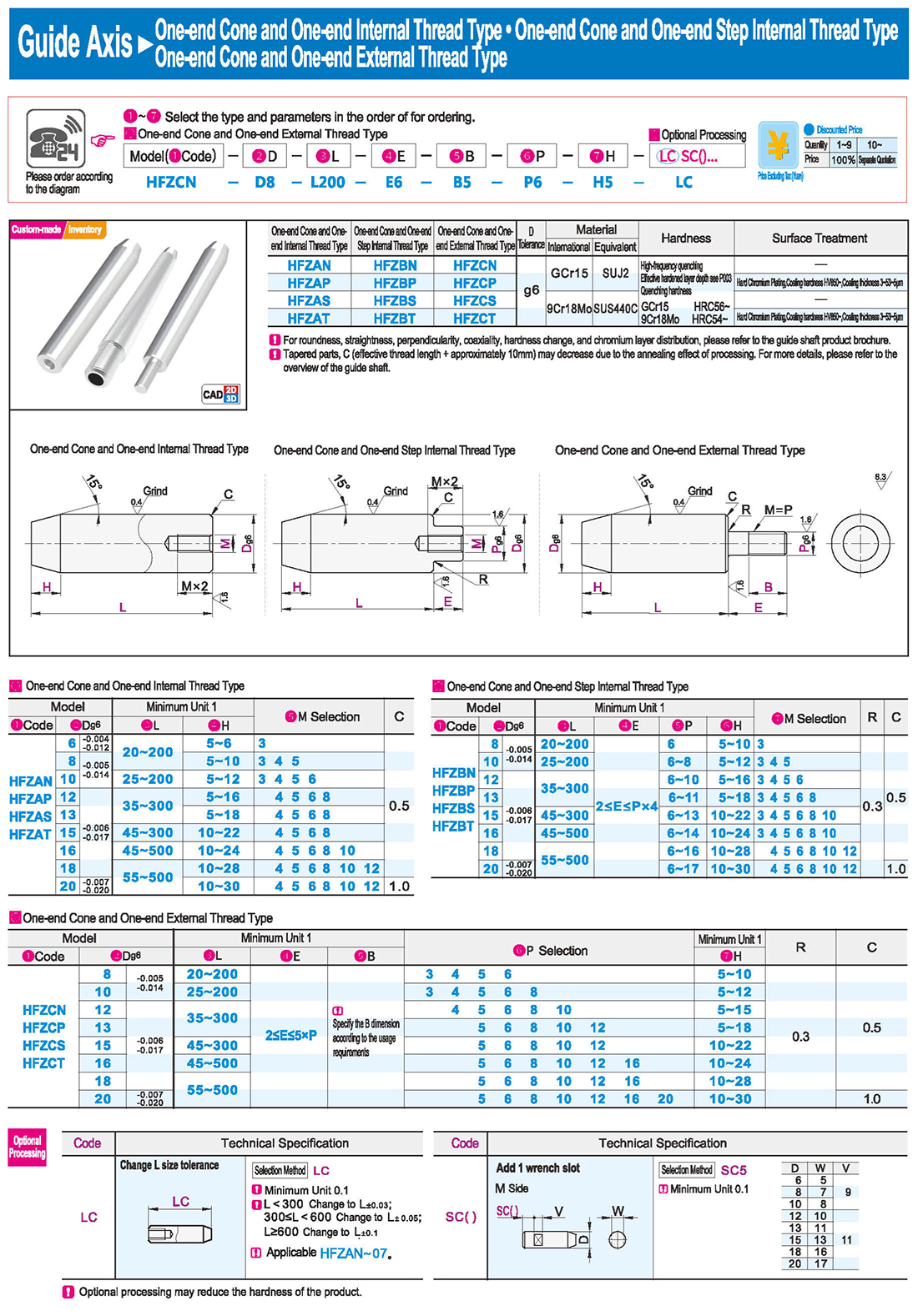
One-end Cone and One-end Internal Thread Type · One-end Cone and One-end Step Internal Thread Type
One-end Cone and One-end External Thread Type
Uniform Diameter Type
Ordinary Grade/Precision Grade One-end External Thread Type
Type with Through Hole
One-end External Thread and One-end Internal Thread Type





 English
 Russian
 Spanish
 Italian
 Arabic
 Korean
 German
 Japanese
 Vietnamese
 Turkish
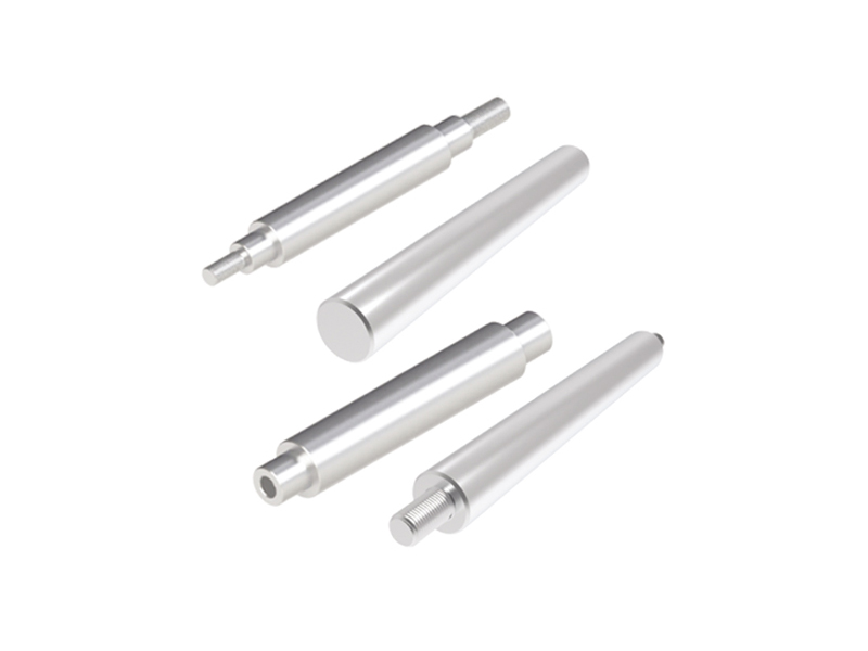
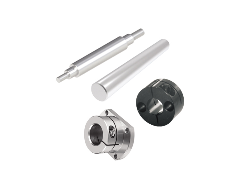
 Introduction
 Specification Table
 Download


