Introduction to Synchronous Pulley Products
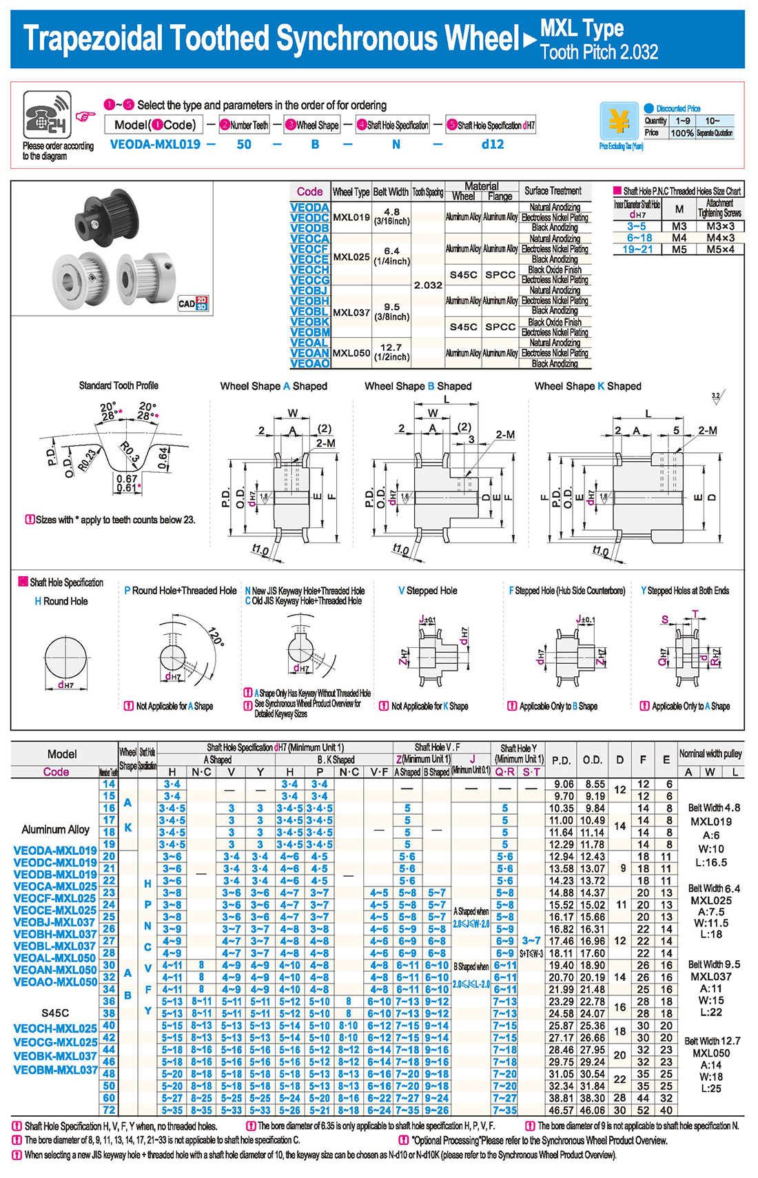
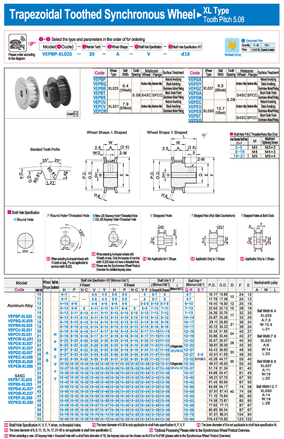
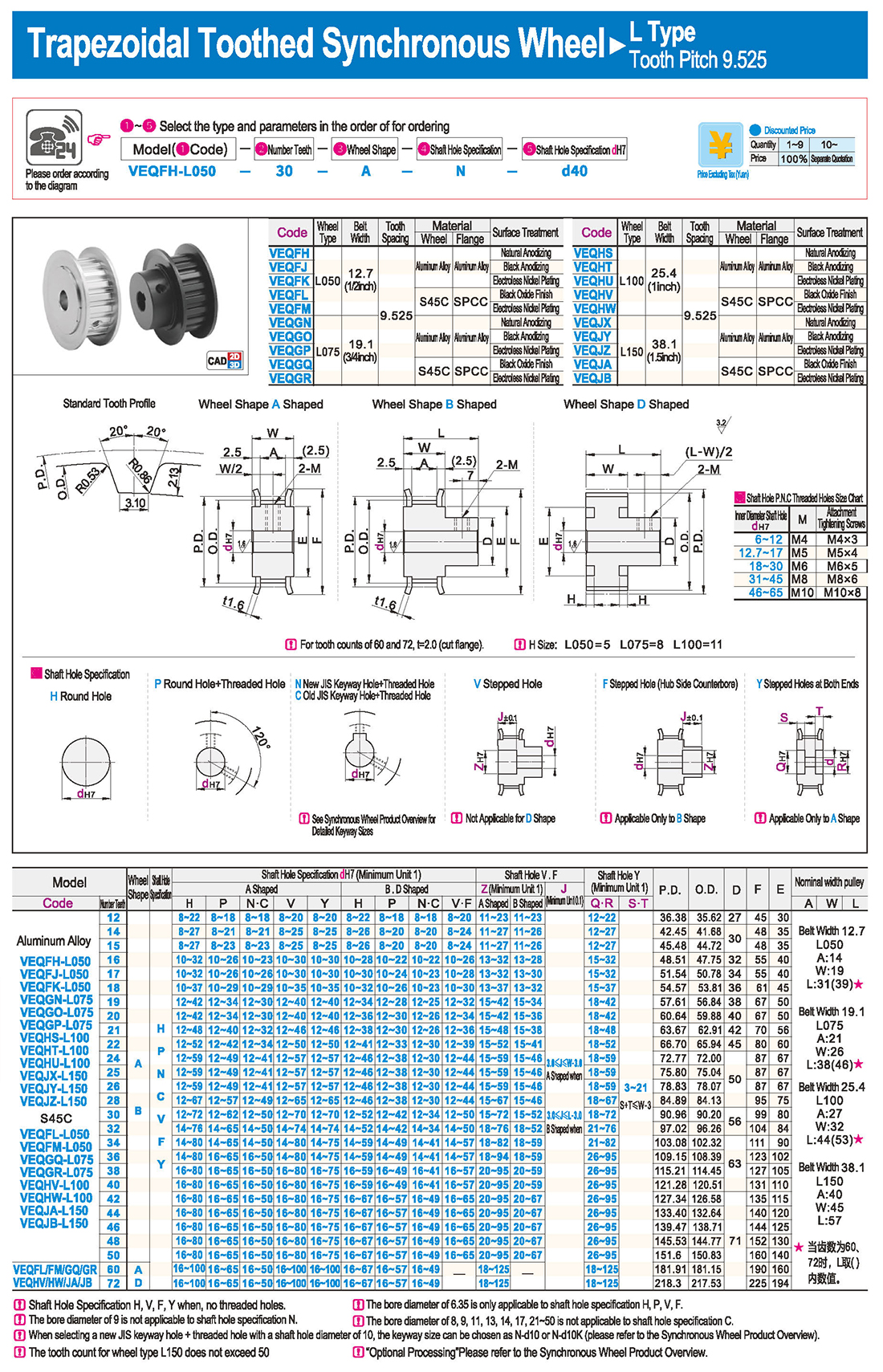
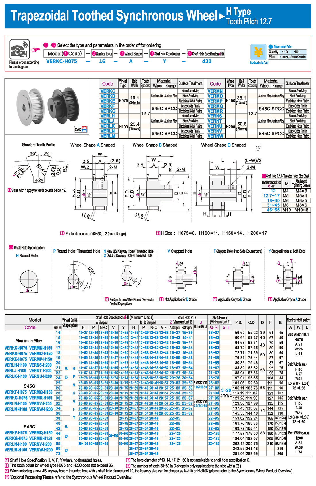
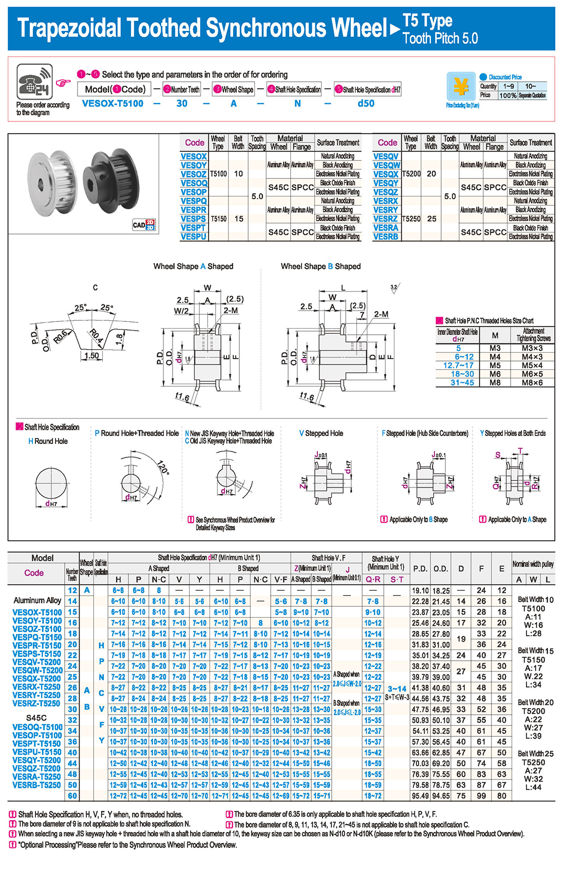
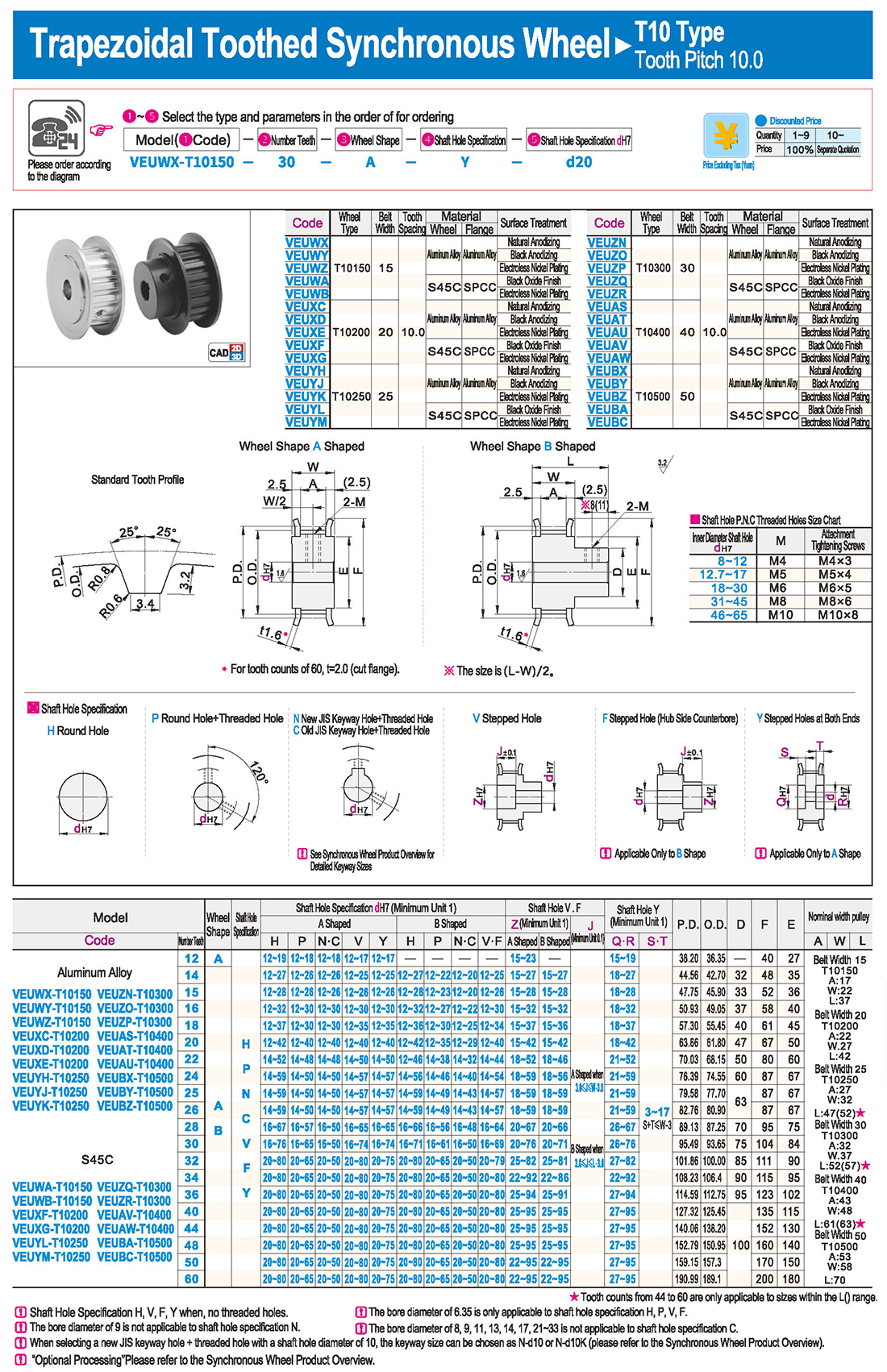
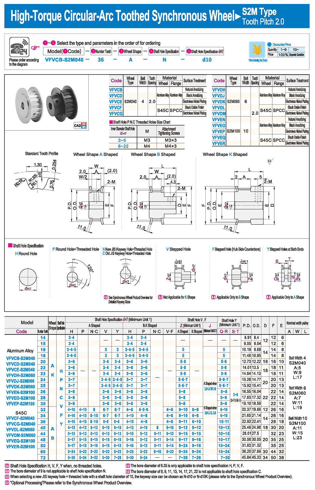
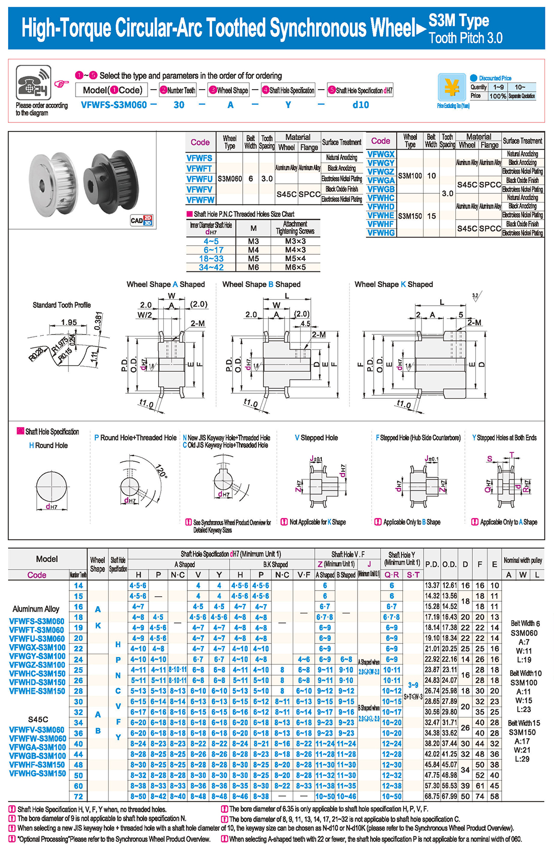
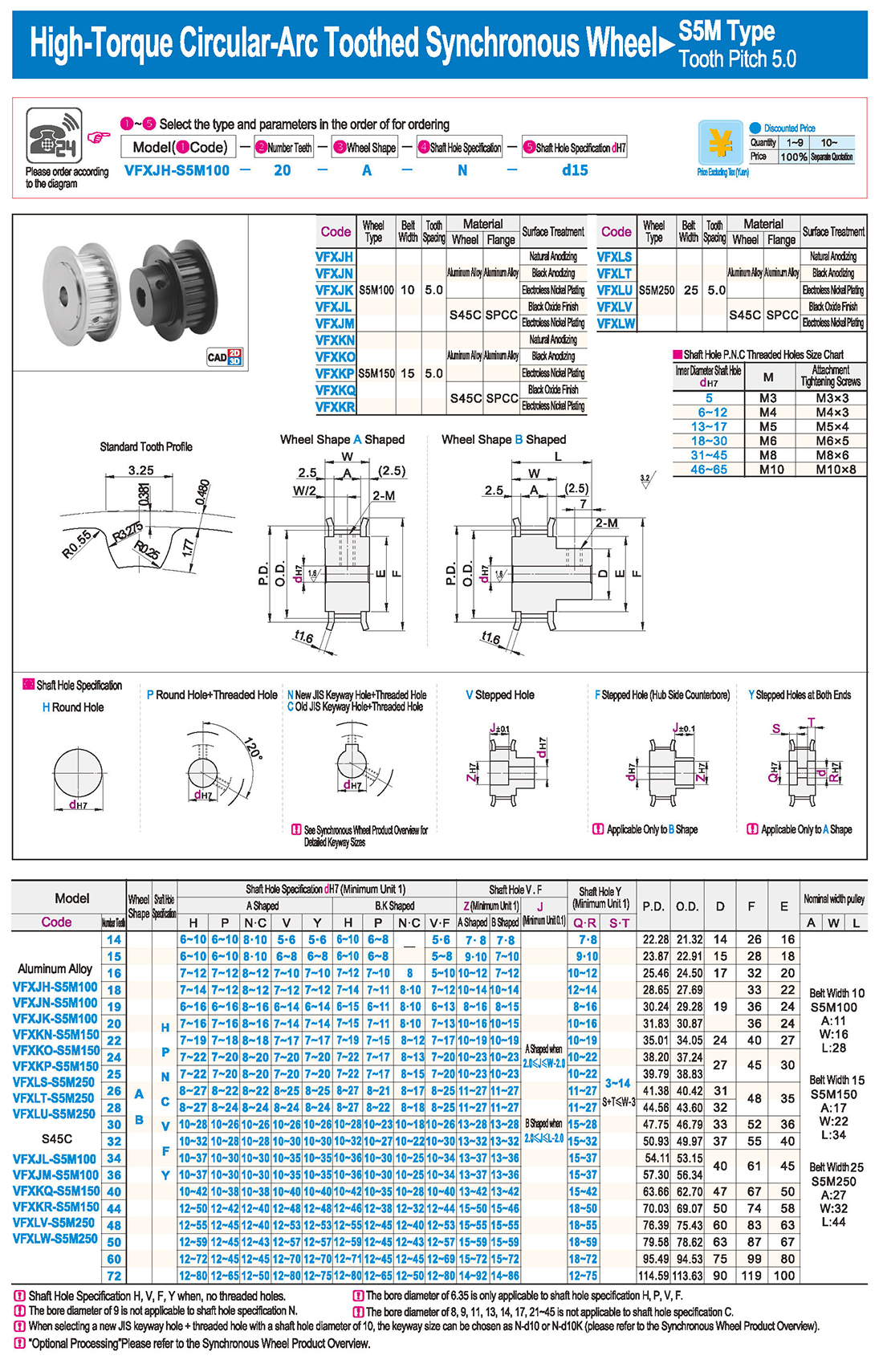
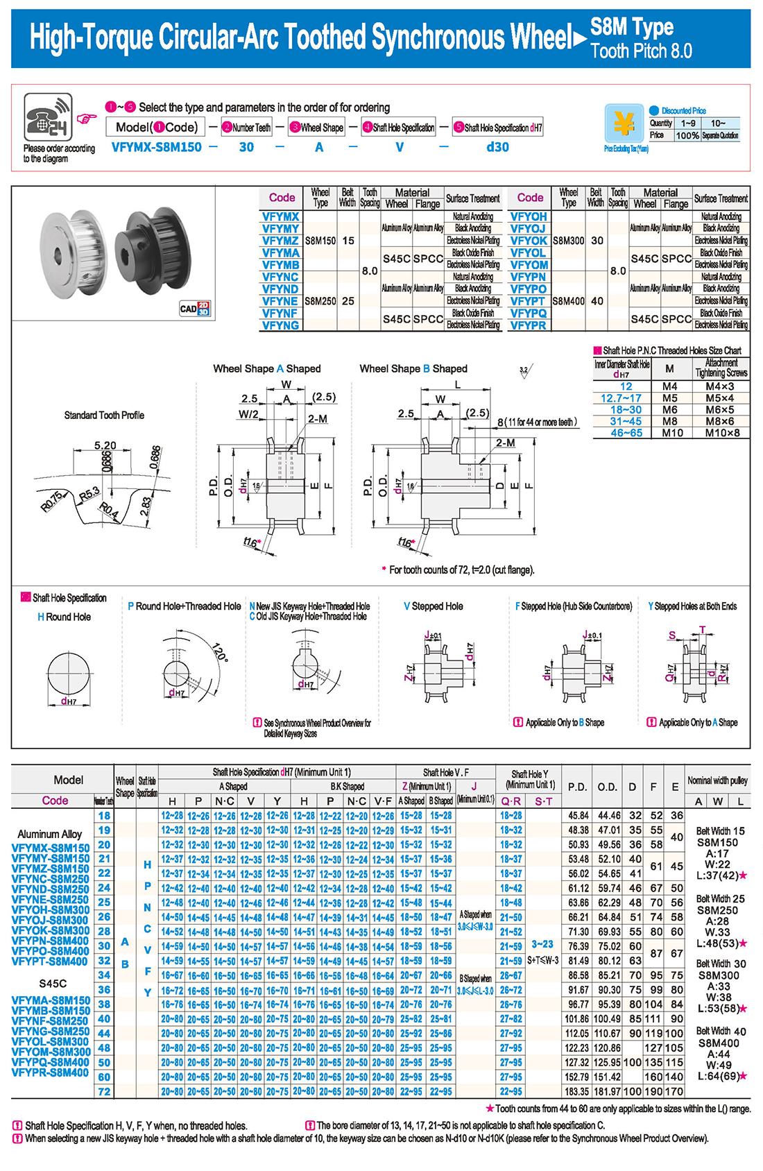
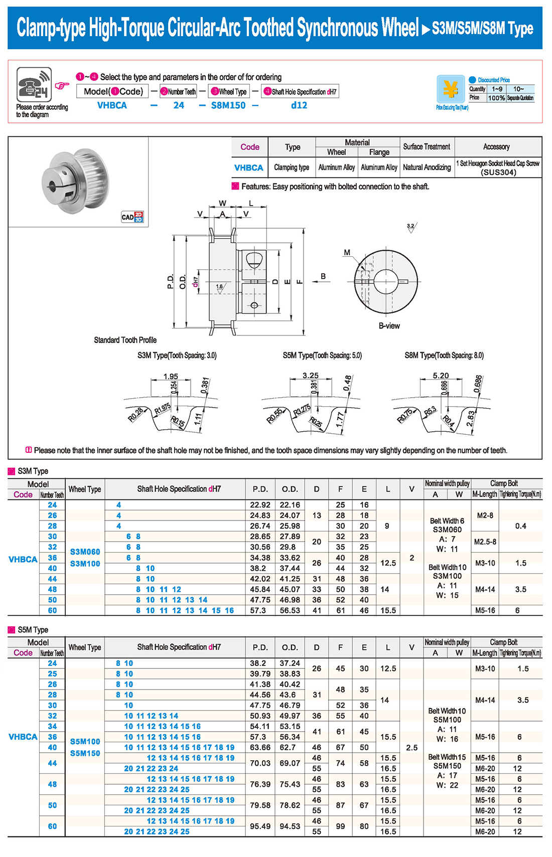
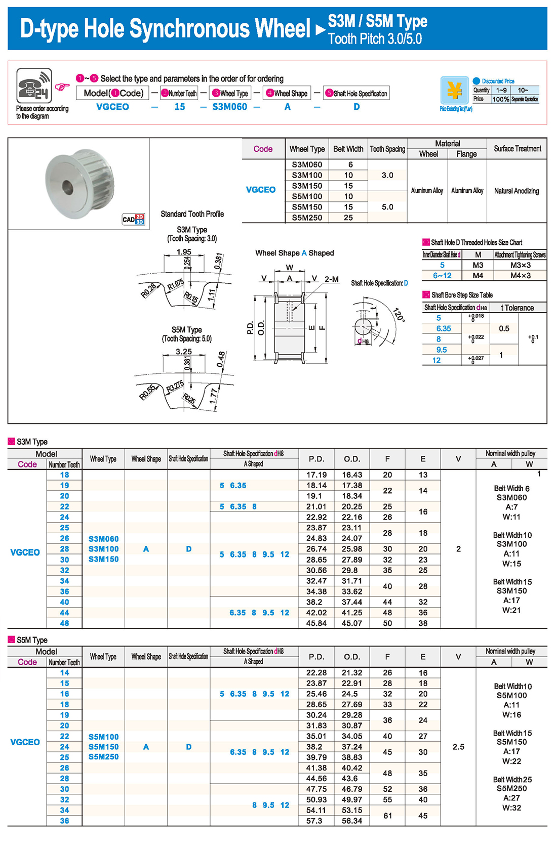
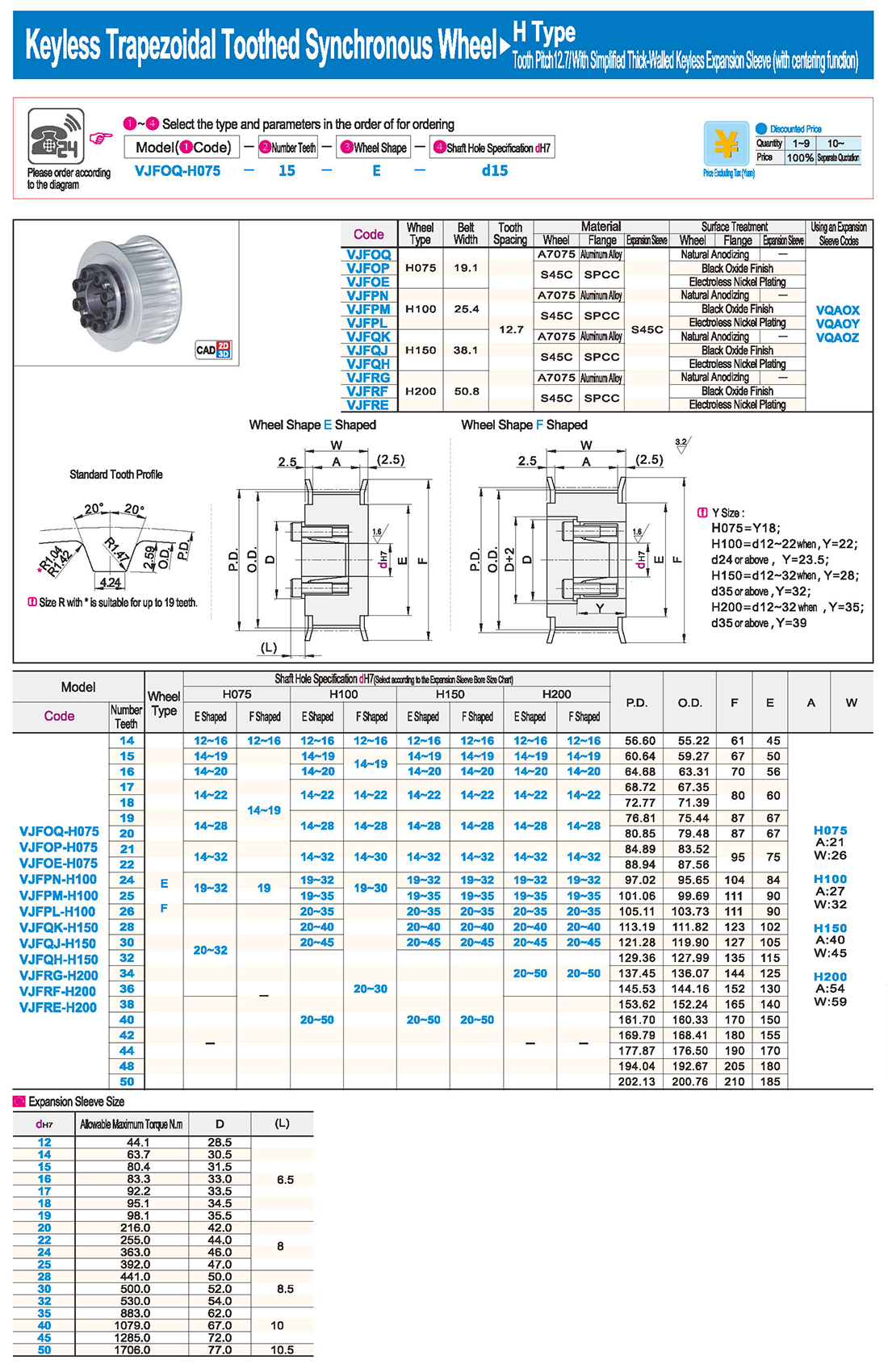
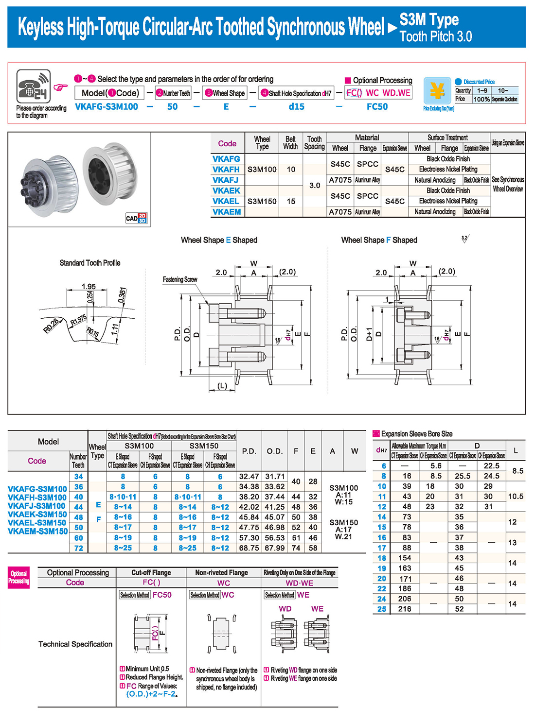
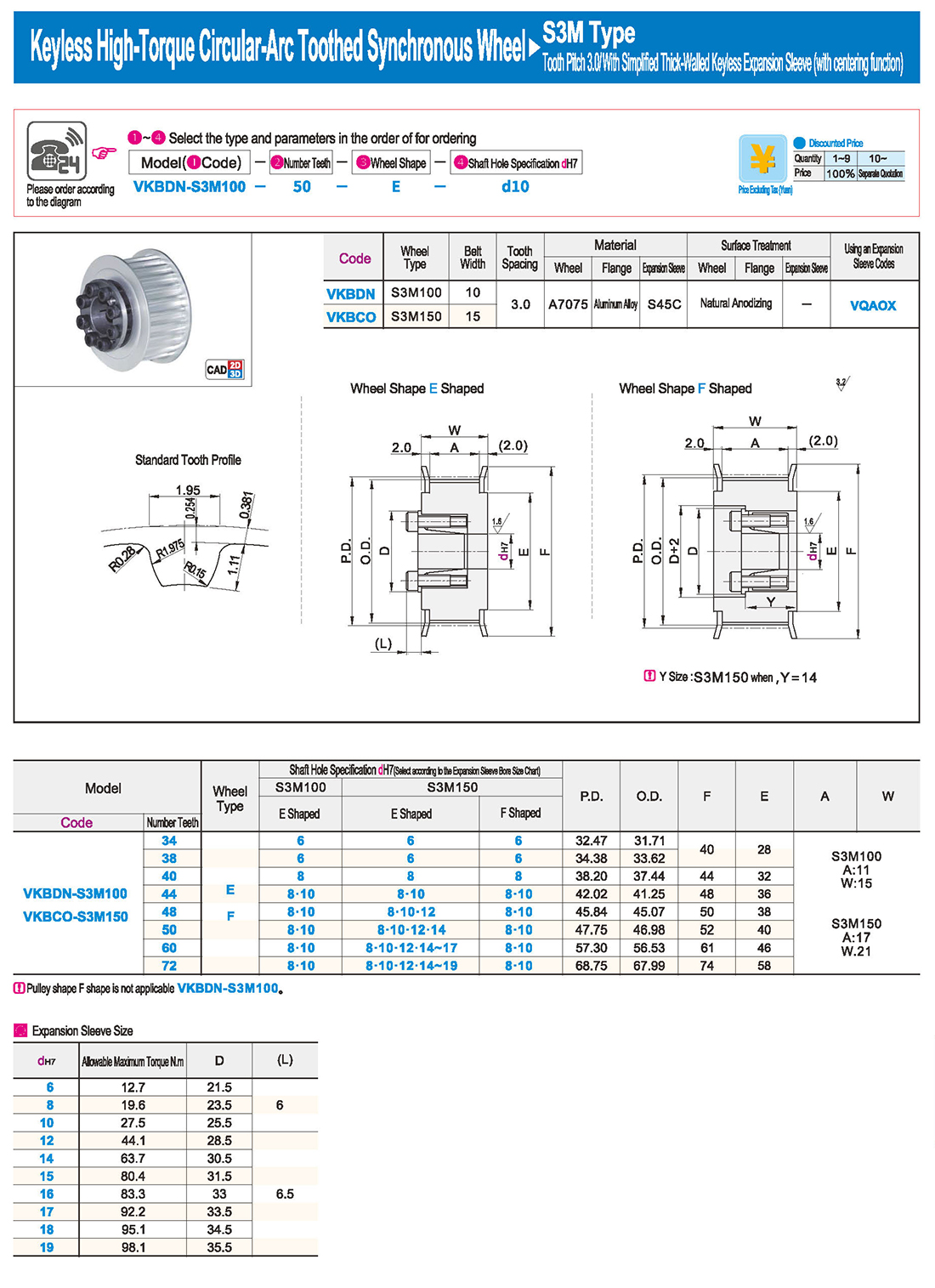
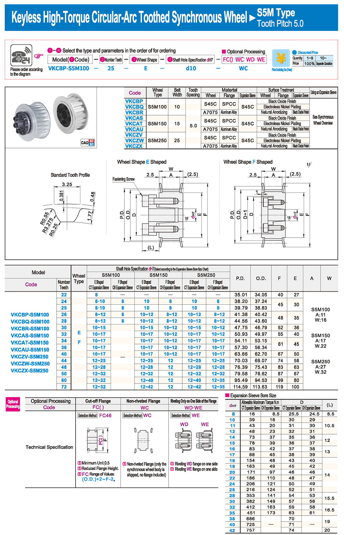
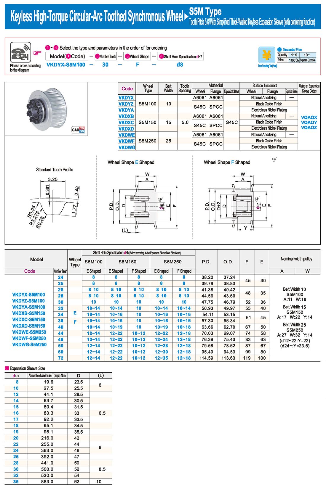
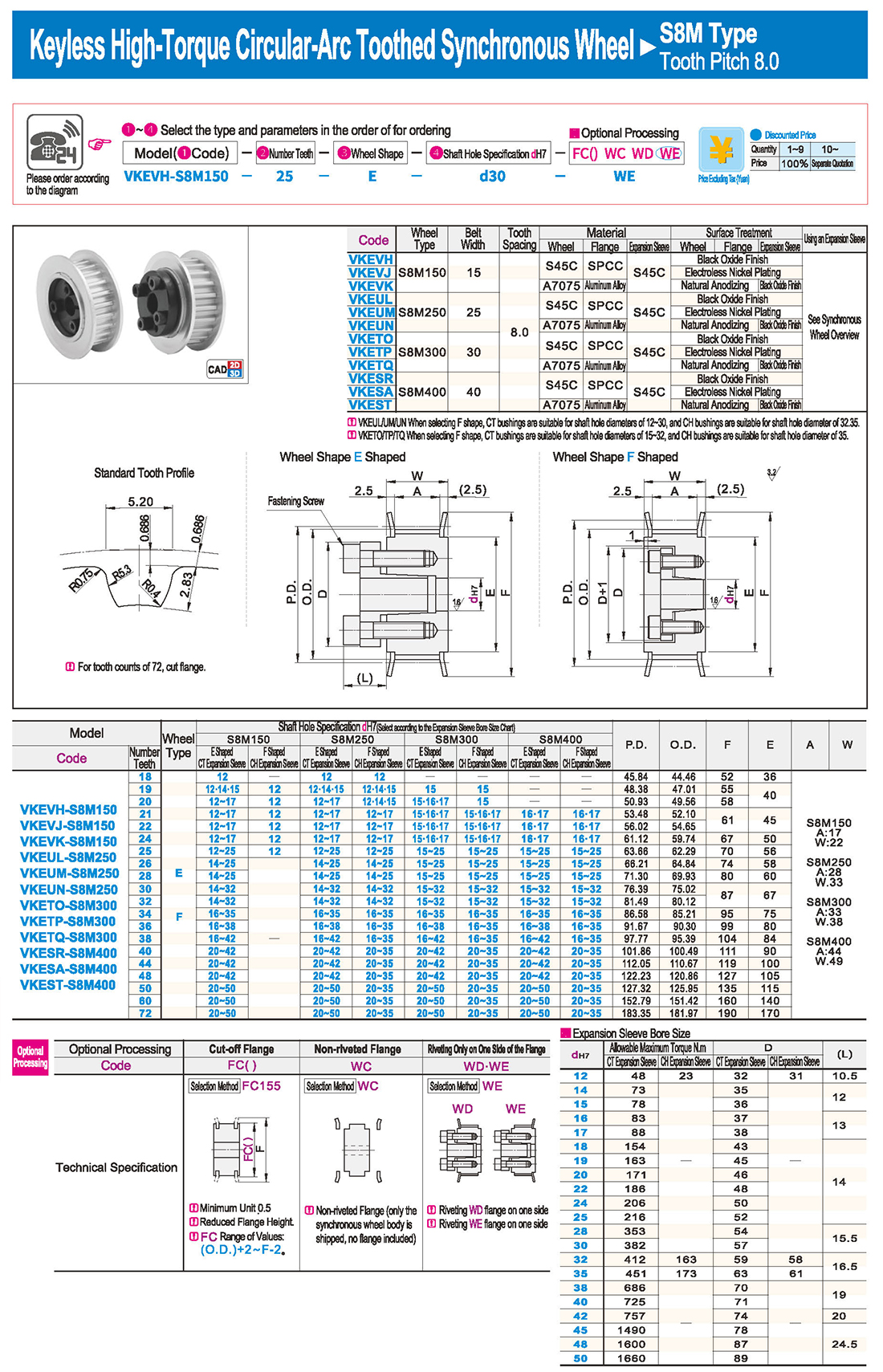
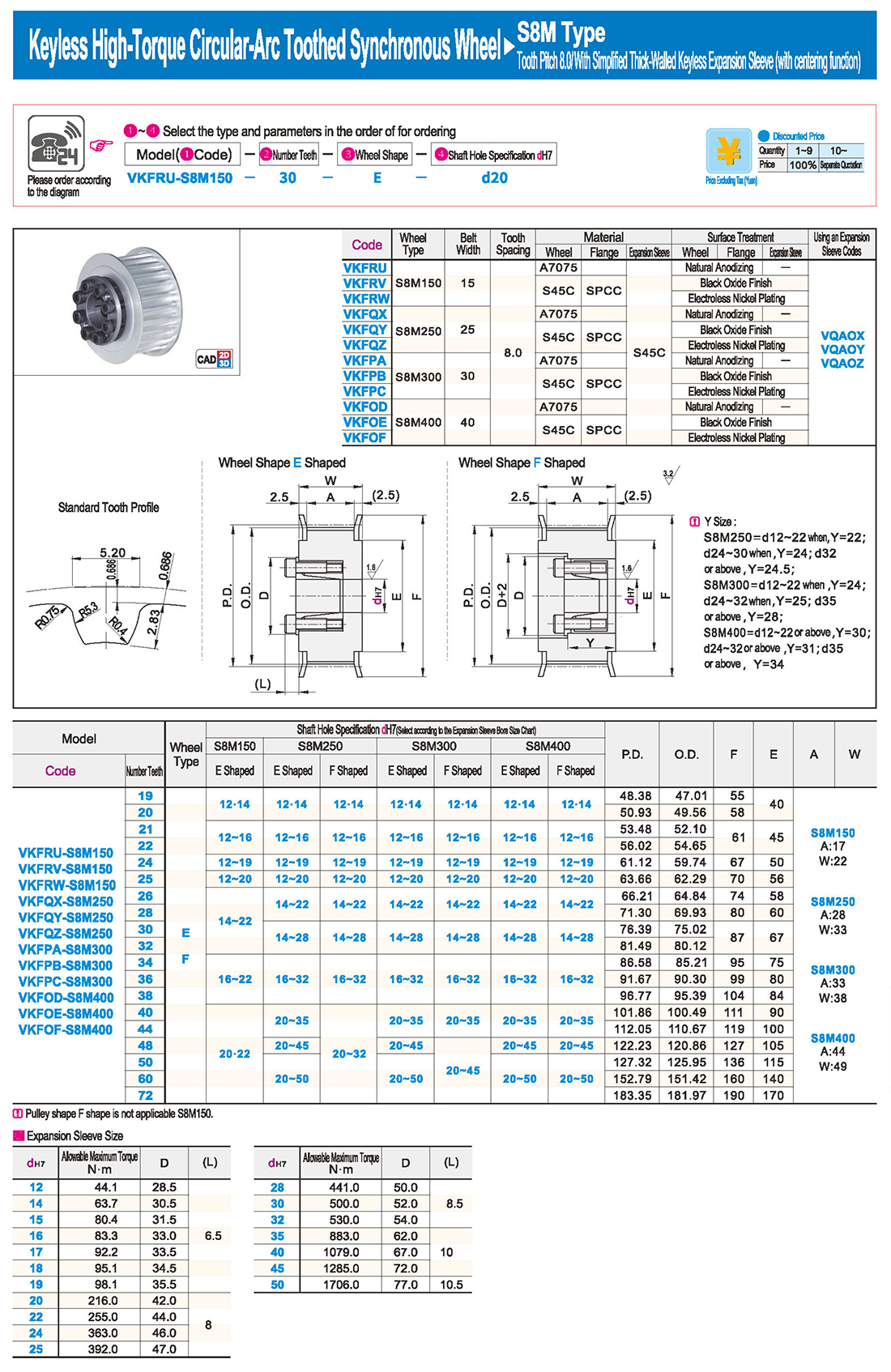
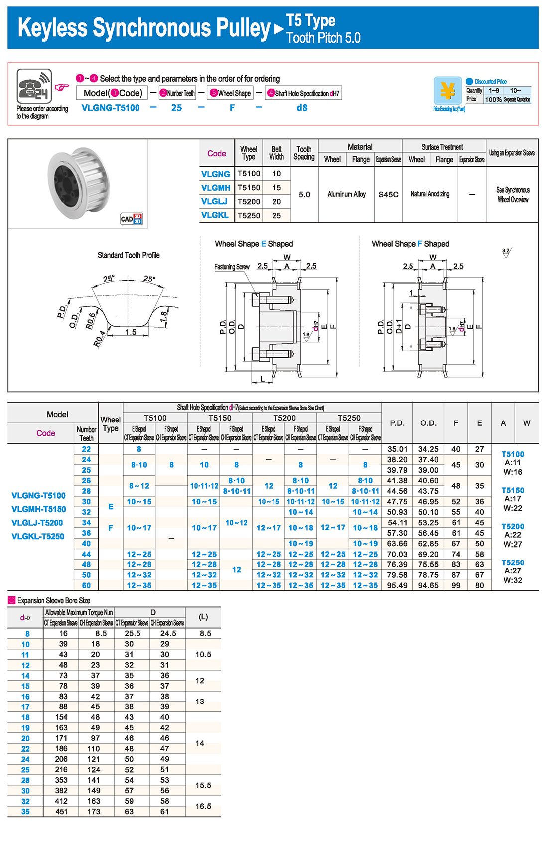
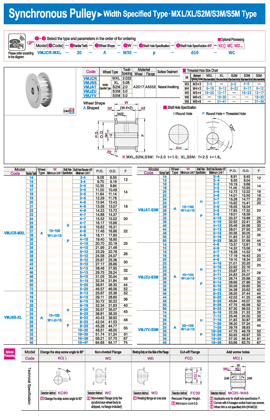
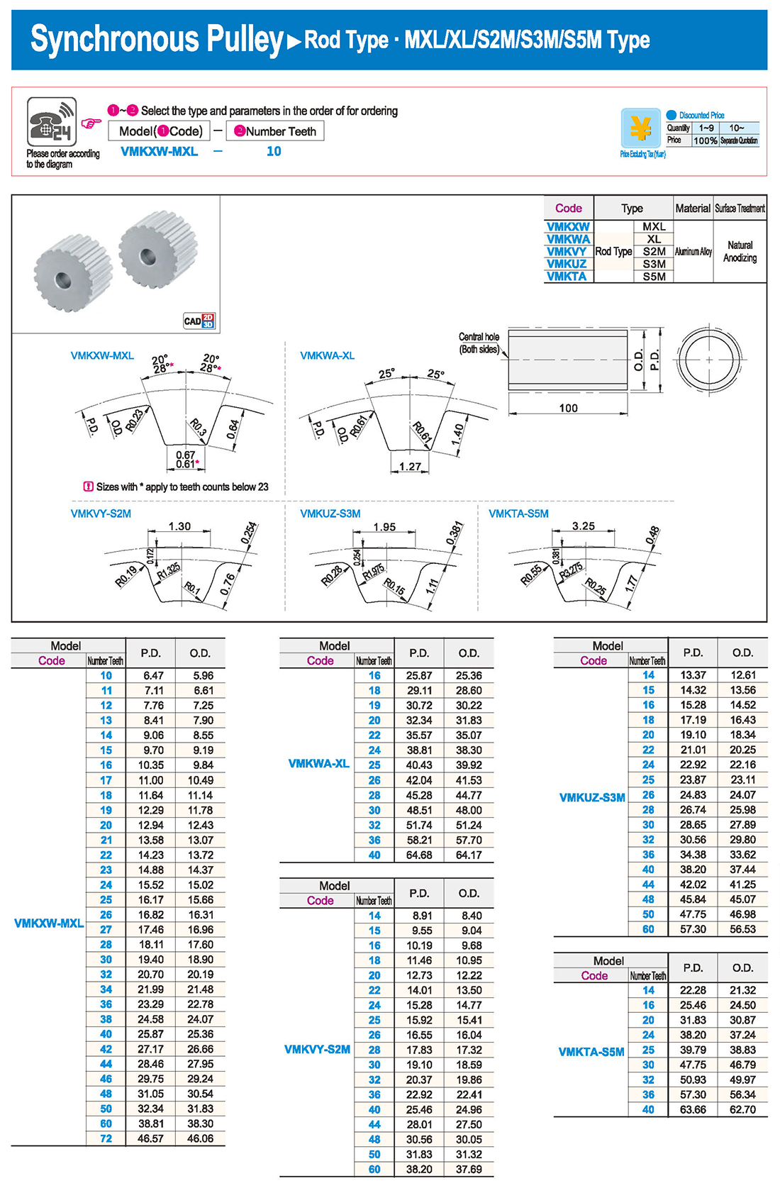
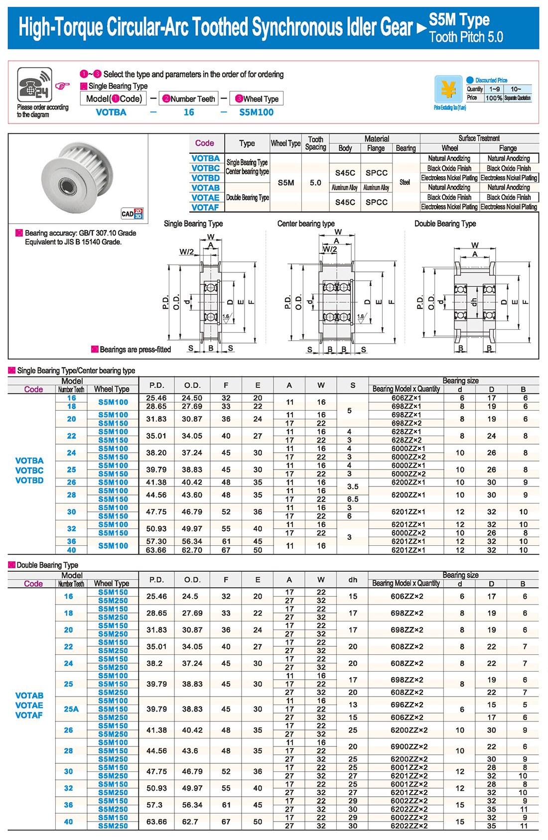
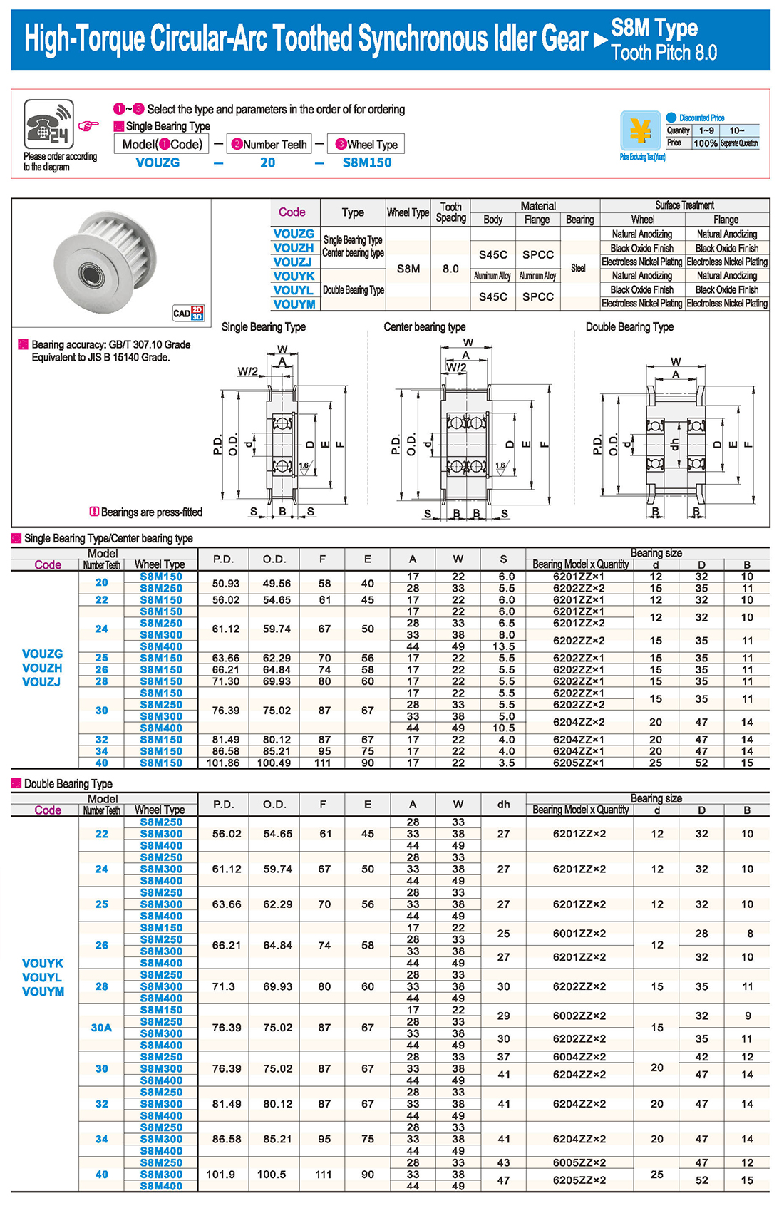
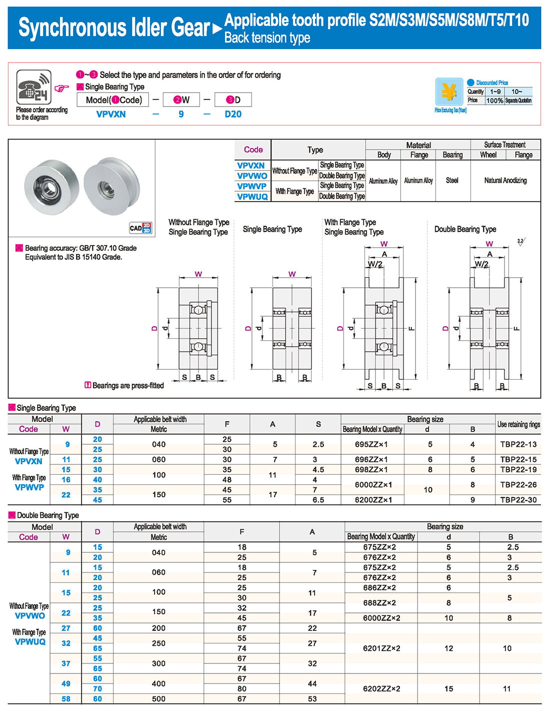
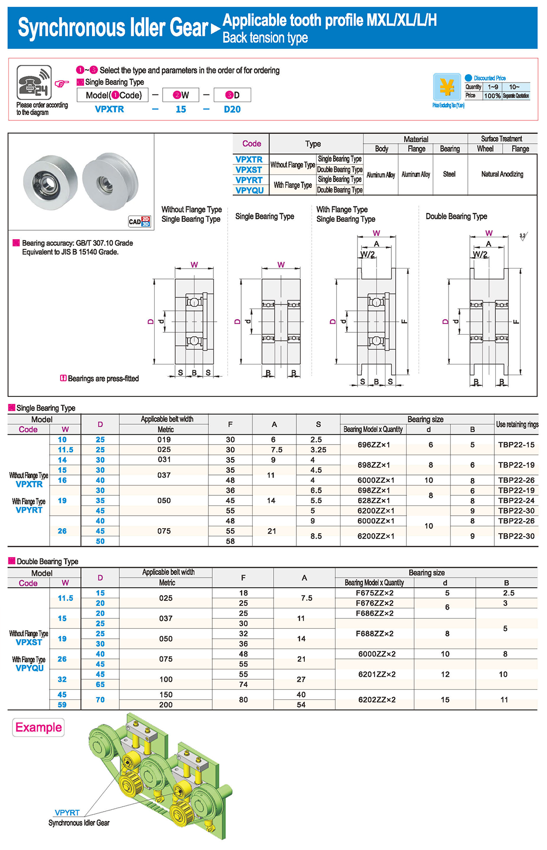
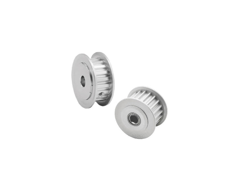
Synchronous pulleys belong to hub-type components, generally with relatively large dimensions, and their manufacturing processes mainly involve casting and forging. Larger-sized pulleys are typically designed with casting methods, using materials such as cast iron (due to its good casting properties), with cast steel seldom used (due to its inferior casting properties). For smaller-sized pulleys, forging is an option, and steel is commonly used as the material. The selection of various indicators and materials for synchronous pulleys follows the principle of minimizing raw materials, ensuring feasible processes, and achieving the lowest cost while meeting usage requirements. Synchronous pulleys are primarily used in scenarios requiring long-distance power transmission, such as the power output of small diesel engines, agricultural vehicles, tractors, automobiles, mining machinery, machining equipment, textile machinery, packaging machinery, lathes, forging presses, small horsepower motorcycle power transmission, agricultural machinery power transmission, air compressors, reducers, generators, ginning machines, and more.
Features
① Accurate transmission, no slipping during operation, and constant transmission ratio.
② Smooth transmission, with cushioning, shock absorption capabilities, and low noise.
③ High transmission efficiency, reaching up to 0.98, with significant energy-saving effects.
④ Convenient maintenance, no lubrication required, and low maintenance costs.
⑤ Wide range of speed ratios, generally up to 10, with linear speeds reaching 50m/s. Capable of transmitting a large power range, from several watts to hundreds of watts.
⑥ Suitable for long-distance transmission, with center distances exceeding 10m.
⑦ Able to operate in locations where pollution is not allowed and the working environment is harsh.
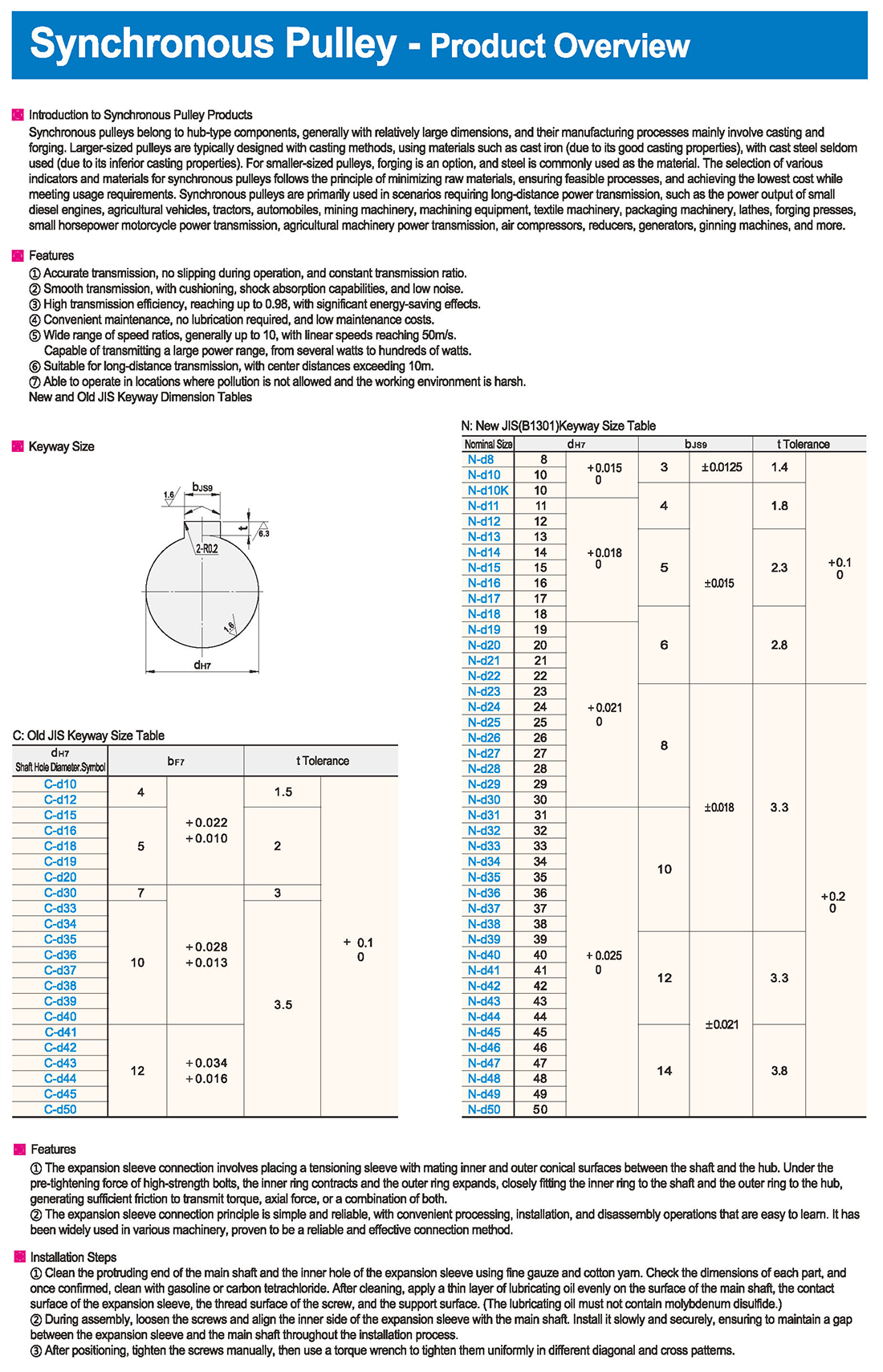
New and Old JIS Keyway Dimension Tables
CAM bearings can withstand large radial and axial loads, as well as impact and vibration loads, suitable for a variety of harsh working environments.
Features
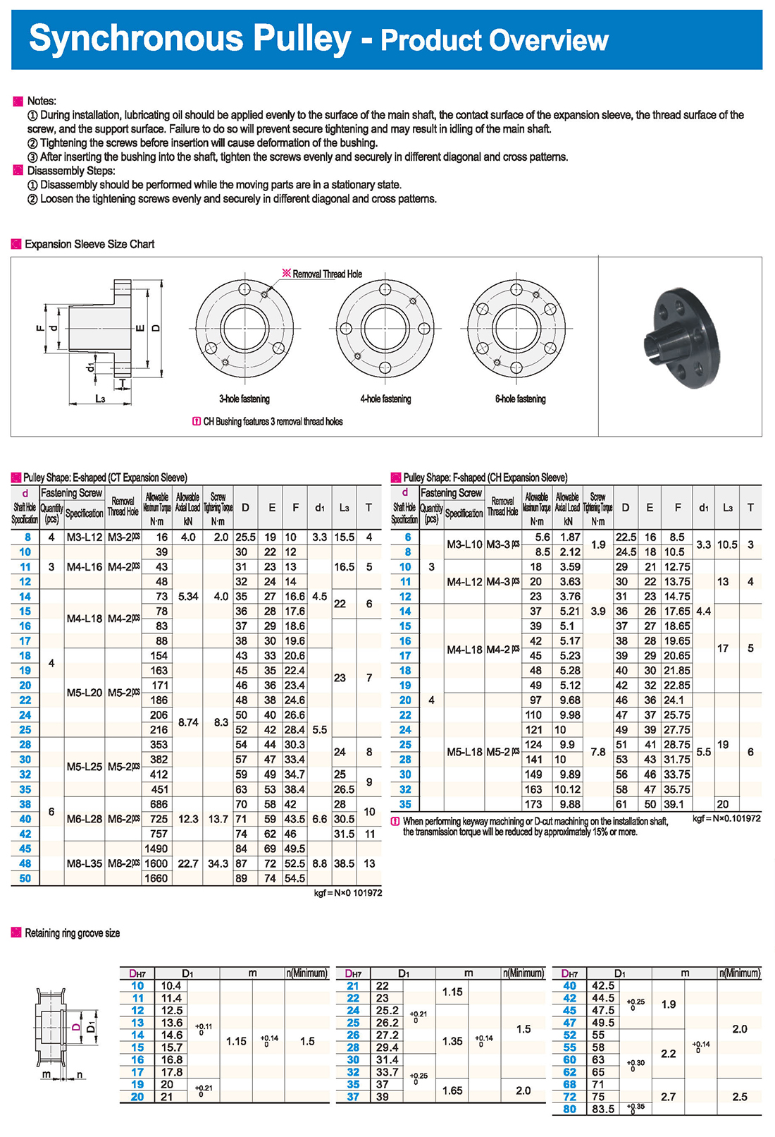
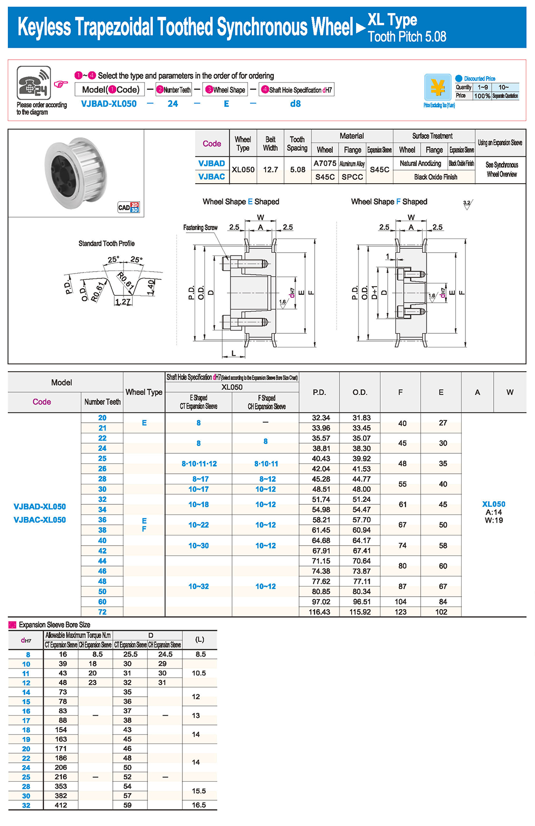
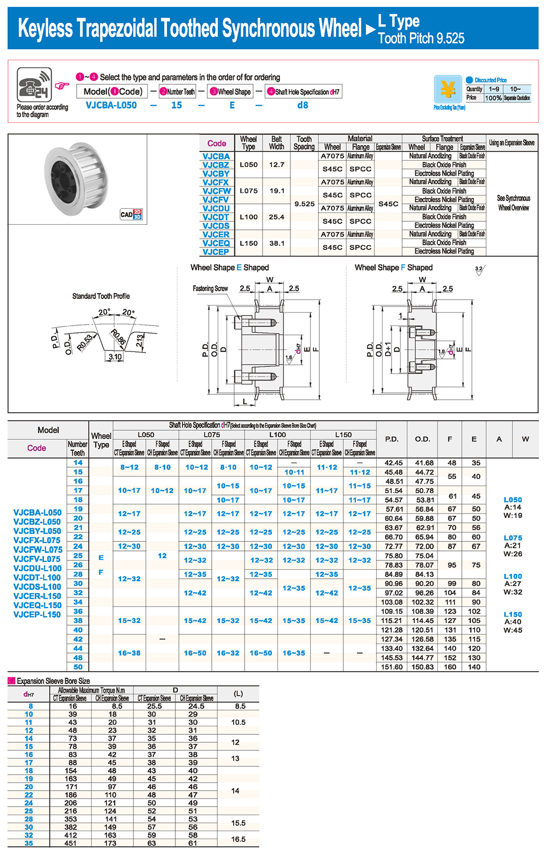
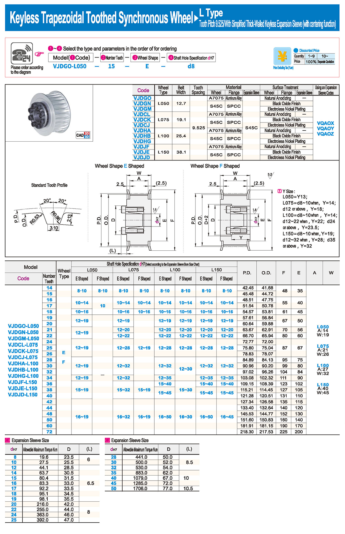
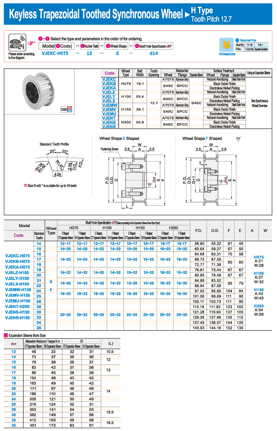
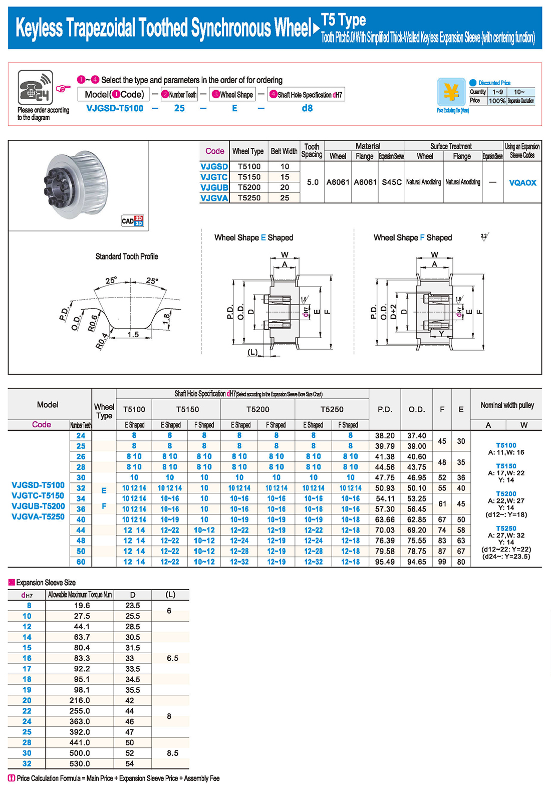
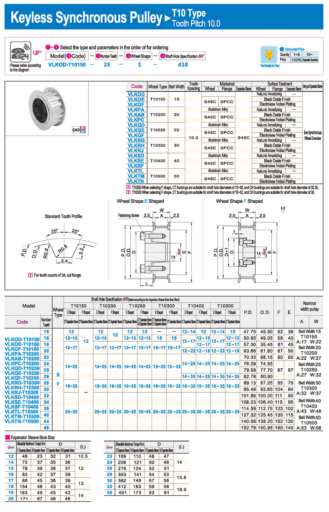
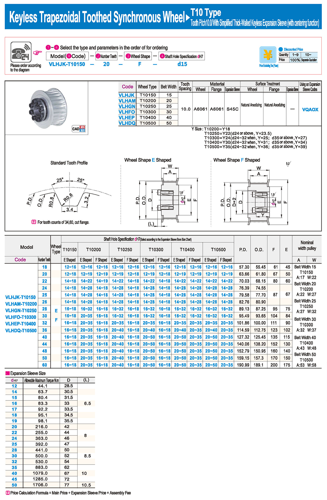
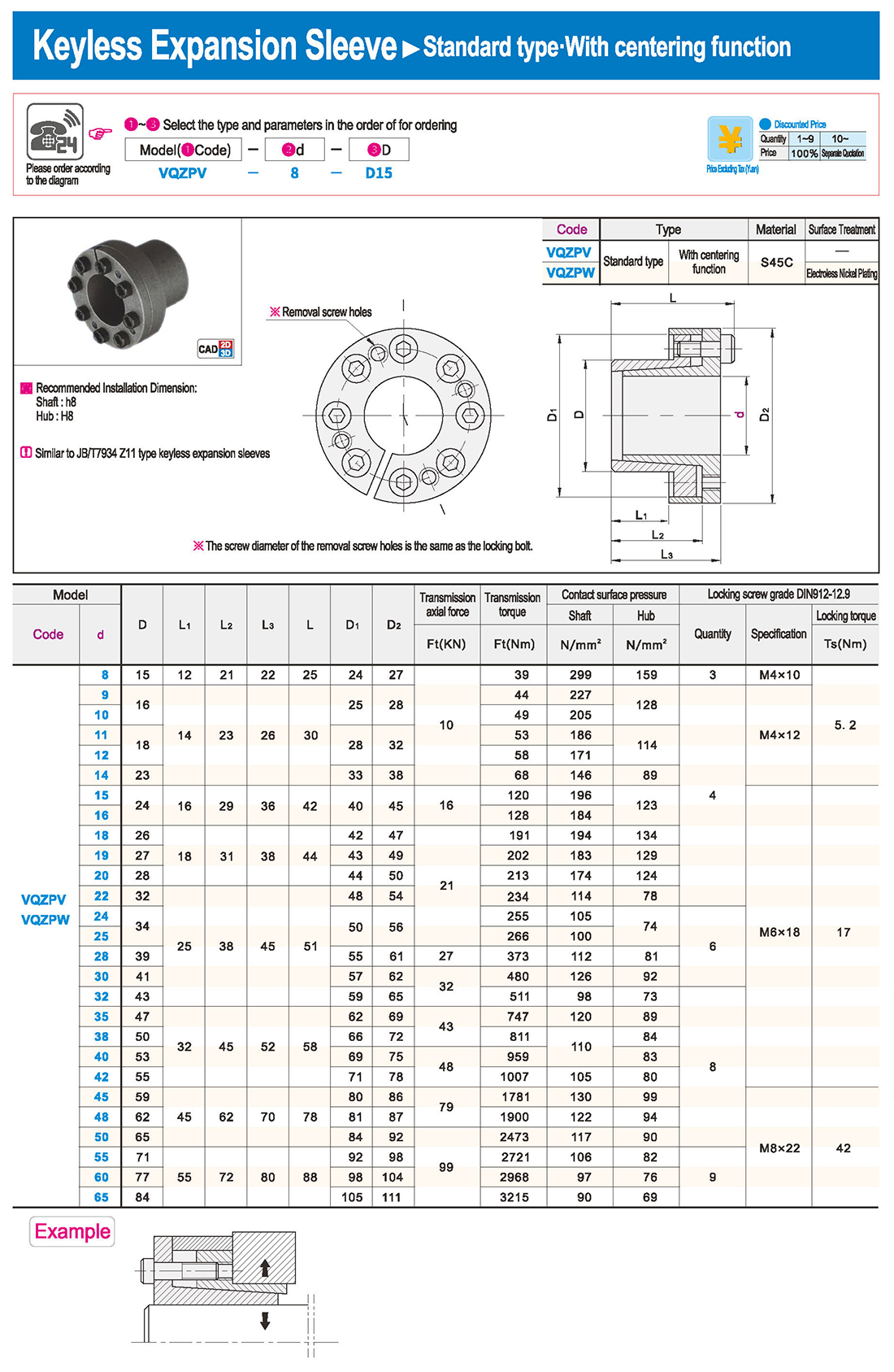
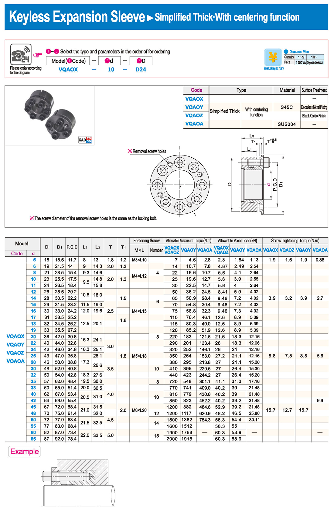
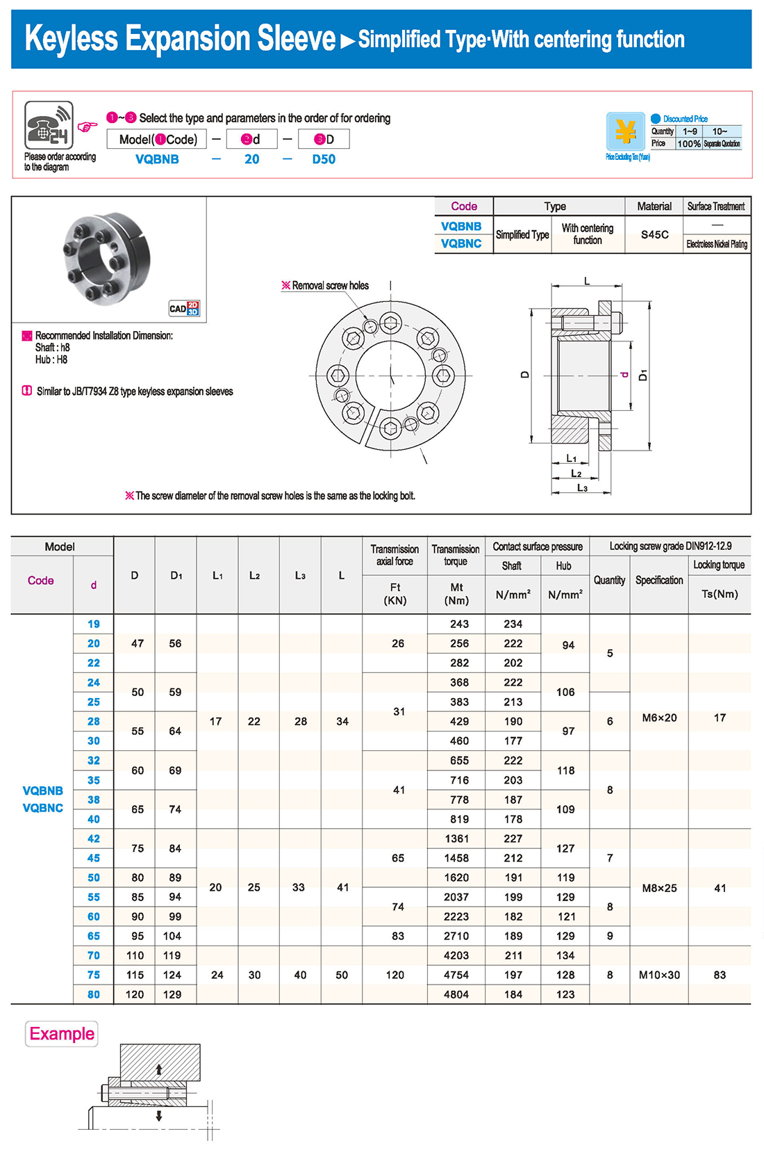
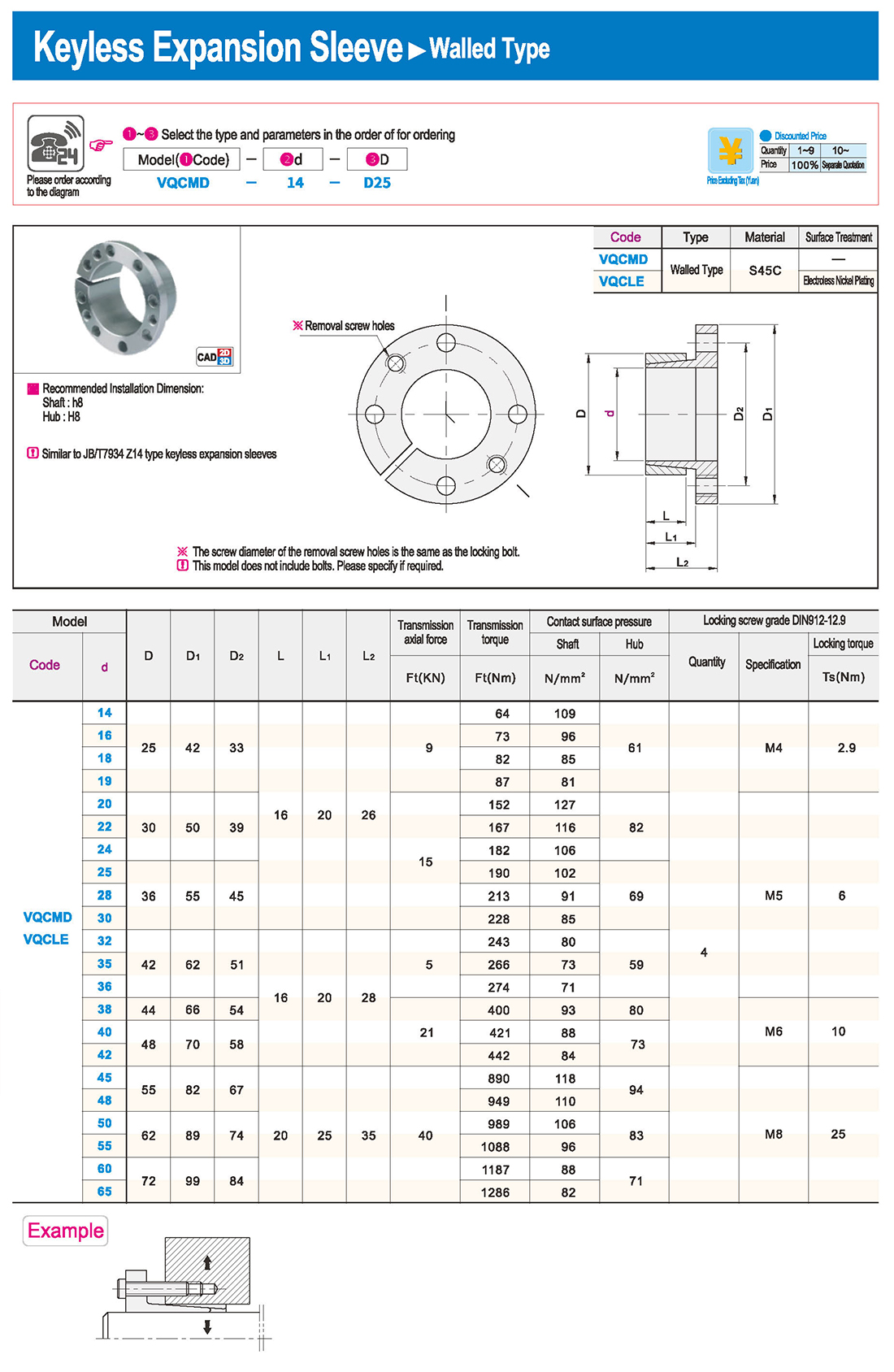
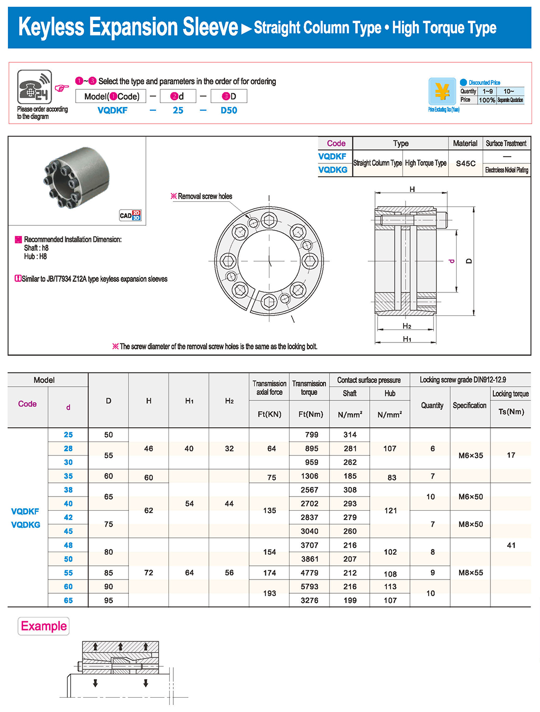
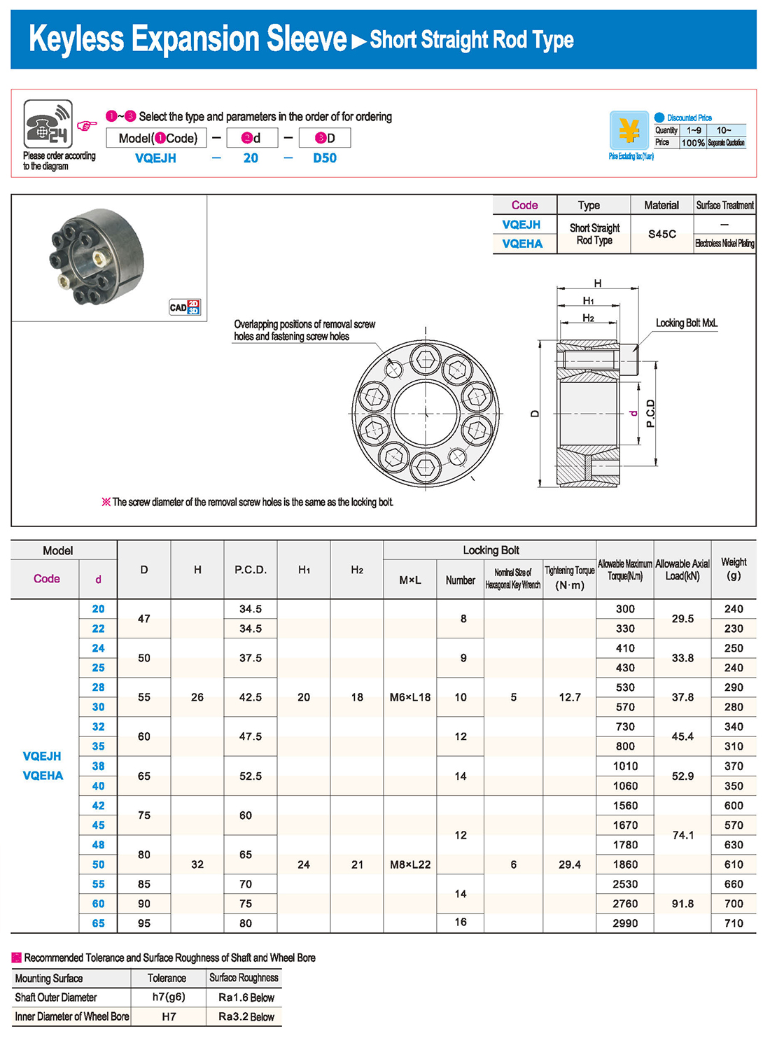
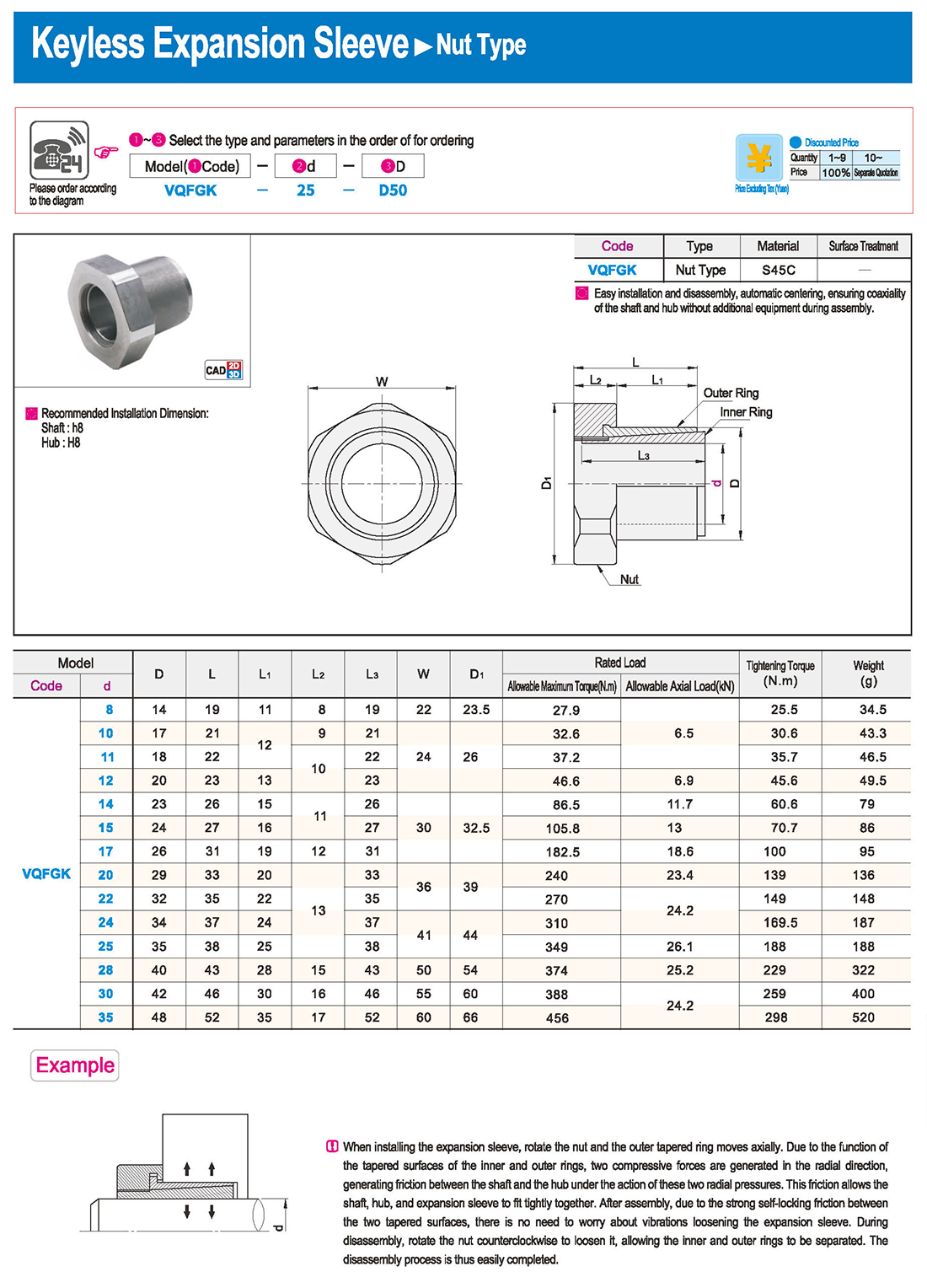
① The expansion sleeve connection involves placing a tensioning sleeve with mating inner and outer conical surfaces between the shaft and the hub. Under the pre-tightening force of high-strength bolts, the inner ring contracts and the outer ring expands, closely fitting the inner ring to the shaft and the outer ring to the hub, generating sufficient friction to transmit torque, axial force, or a combination of both.
② The expansion sleeve connection principle is simple and reliable, with convenient processing, installation, and disassembly operations that are easy to learn. It has been widely used in various machinery, proven to be a reliable and effective connection method.
Installation Steps
① Clean the protruding end of the main shaft and the inner hole of the expansion sleeve using fine gauze and cotton yarn. Check the dimensions of each part, and once confirmed, clean with gasoline or carbon tetrachloride. After cleaning, apply a thin layer of lubricating oil evenly on the surface of the main shaft, the contact surface of the expansion sleeve, the thread surface of the screw, and the support surface. (The lubricating oil must not contain molybdenum disulfide.)
② During assembly, loosen the screws and align the inner side of the expansion sleeve with the main shaft. Install it slowly and securely, ensuring to maintain a gap between the expansion sleeve and the main shaft throughout the installation process.
③ After positioning, tighten the screws manually, then use a torque wrench to tighten them uniformly in different diagonal and cross patterns.
Notes:
① During installation, lubricating oil should be applied evenly to the surface of the main shaft, the contact surface of the expansion sleeve, the thread surface of the screw, and the support surface. Failure to do so will prevent secure tightening and may result in idling of the main shaft.
② Tightening the screws before insertion will cause deformation of the bushing.
③ After inserting the bushing into the shaft, tighten the screws evenly and securely in different diagonal and cross patterns.
Disassembly Steps:
① Disassembly should be performed while the moving parts are in a stationary state.
② Loosen the tightening screws evenly and securely in different diagonal and cross patterns.



 English
 Russian
 Spanish
 Italian
 Arabic
 Korean
 German
 Japanese
 Vietnamese
 Turkish
 Introduction
 Specification Table
 Download


